The Scientist and Engineer's Guide to
Digital Signal Processing
By Steven W. Smith, Ph.D.
Book Search
Table of contents
- 1: The Breadth and Depth of DSP
- 2: Statistics, Probability and Noise
- 3: ADC and DAC
- 4: DSP Software
- 5: Linear Systems
- 6: Convolution
- 7: Properties of Convolution
- 8: The Discrete Fourier Transform
- 9: Applications of the DFT
- 10: Fourier Transform Properties
- 11: Fourier Transform Pairs
- 12: The Fast Fourier Transform
- 13: Continuous Signal Processing
- 14: Introduction to Digital Filters
- 15: Moving Average Filters
- 16: Windowed-Sinc Filters
- 17: Custom Filters
- 18: FFT Convolution
- 19: Recursive Filters
- 20: Chebyshev Filters
- 21: Filter Comparison
- 22: Audio Processing
- 23: Image Formation & Display
- 24: Linear Image Processing
- 25: Special Imaging Techniques
- 26: Neural Networks (and more!)
- 27: Data Compression
- 28: Digital Signal Processors
- 29: Getting Started with DSPs
- 30: Complex Numbers
- 31: The Complex Fourier Transform
- 32: The Laplace Transform
- 33: The z-Transform
- 34: Explaining Benford's Law
How to order your own hardcover copy
Wouldn't you rather have a bound book instead of 640 loose pages?Your laser printer will thank you!
Order from Amazon.com.
Chapter 8: The Discrete Fourier Transform
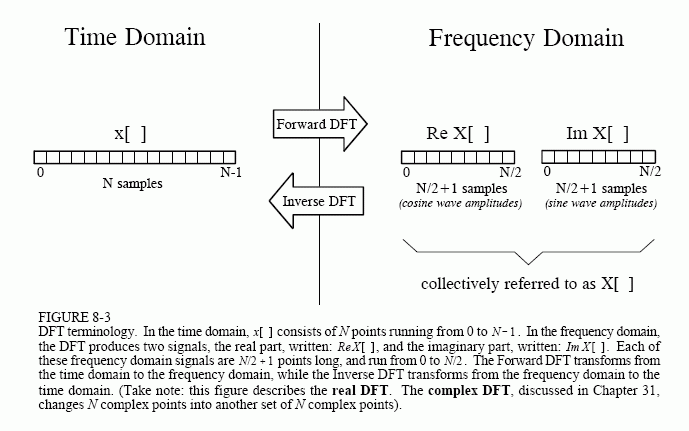
As shown in Fig. 8-3, the discrete Fourier transform changes an N point input signal into two point output signals. The input signal contains the signal being decomposed, while the two output signals contain the amplitudes of the component sine and cosine waves (scaled in a way we will discuss shortly). The input signal is said to be in the time domain. This is because the most common type of signal entering the DFT is composed of

samples taken at regular intervals of time. Of course, any kind of sampled data can be fed into the DFT, regardless of how it was acquired. When you see the term "time domain" in Fourier analysis, it may actually refer to samples taken over time, or it might be a general reference to any discrete signal that is being decomposed. The term frequency domain is used to describe the amplitudes of the sine and cosine waves (including the special scaling we promised to explain).
The frequency domain contains exactly the same information as the time domain, just in a different form. If you know one domain, you can calculate the other. Given the time domain signal, the process of calculating the frequency domain is called decomposition, analysis, the forward DFT, or simply, the DFT. If you know the frequency domain, calculation of the time domain is called synthesis, or the inverse DFT. Both synthesis and analysis can be represented in equation form and computer algorithms.
The number of samples in the time domain is usually represented by the variable N. While N can be any positive integer, a power of two is usually chosen, i.e., 128, 256, 512, 1024, etc. There are two reasons for this. First, digital data storage uses binary addressing, making powers of two a natural signal length. Second, the most efficient algorithm for calculating the DFT, the Fast Fourier Transform (FFT), usually operates with N that is a power of two. Typically, N is selected between 32 and 4096. In most cases, the samples run from 0 to N-1, rather than 1 to N.
Standard DSP notation uses lower case letters to represent time domain signals, such as x[ ], y[ ], and z[ ]. The corresponding upper case letters are used to represent their frequency domains, that is, X[ ], Y[ ], and Z[ ]. For illustration, assume an N point time domain signal is contained in x[n]. The frequency domain of this signal is called X[ ], and consists of two parts, each an array of N/2 +1 samples. These are called the Real part of X[ ] , written as: ReX[ ], and the Imaginary part of X[ ], written as: ImX[ ]. The values in ReX[ ] are the amplitudes of the cosine waves, while the values in ImX[ ] are the amplitudes of the sine waves (not worrying about the scaling factors for the moment). Just as the time domain runs from x[n] to x[N-1], the frequency domain signals run from ReX[0] to ReX[N/2], and from ImX[0] to ImX[N/2]. Study these notations carefully; they are critical to understanding the equations in DSP. Unfortunately, some computer languages don't distinguish between lower and upper case, making the variable names up to the individual programmer. The programs in this book use the array XX[ ] to hold the time domain signal, and the arrays REX[ ] and IMX[ ] to hold the frequency domain signals.
The names real part and imaginary part originate from the complex DFT, where they are used to distinguish between real and imaginary numbers. Nothing so complicated is required for the real DFT. Until you get to Chapter 29, simply think that "real part" means the cosine wave amplitudes, while "imaginary part" means the sine wave amplitudes. Don't let these suggestive names mislead you; everything here uses ordinary numbers.
Likewise, don't be misled by the lengths of the frequency domain signals. It is common in the DSP literature to see statements such as: "The DFT changes an N point time domain signal into an N point frequency domain signal." This is referring to the complex DFT, where each "point" is a complex number (consisting of real and imaginary parts). For now, focus on learning the real DFT, the difficult math will come soon enough.
