The Scientist and Engineer's Guide to
Digital Signal Processing
By Steven W. Smith, Ph.D.
Book Search
Table of contents
- 1: The Breadth and Depth of DSP
- 2: Statistics, Probability and Noise
- 3: ADC and DAC
- 4: DSP Software
- 5: Linear Systems
- 6: Convolution
- 7: Properties of Convolution
- 8: The Discrete Fourier Transform
- 9: Applications of the DFT
- 10: Fourier Transform Properties
- 11: Fourier Transform Pairs
- 12: The Fast Fourier Transform
- 13: Continuous Signal Processing
- 14: Introduction to Digital Filters
- 15: Moving Average Filters
- 16: Windowed-Sinc Filters
- 17: Custom Filters
- 18: FFT Convolution
- 19: Recursive Filters
- 20: Chebyshev Filters
- 21: Filter Comparison
- 22: Audio Processing
- 23: Image Formation & Display
- 24: Linear Image Processing
- 25: Special Imaging Techniques
- 26: Neural Networks (and more!)
- 27: Data Compression
- 28: Digital Signal Processors
- 29: Getting Started with DSPs
- 30: Complex Numbers
- 31: The Complex Fourier Transform
- 32: The Laplace Transform
- 33: The z-Transform
- 34: Explaining Benford's Law
How to order your own hardcover copy
Wouldn't you rather have a bound book instead of 640 loose pages?Your laser printer will thank you!
Order from Amazon.com.
Chapter 22: Audio Processing
Digital filtering can improve audio signals in many ways. For instance, Wiener filtering can be used to separate frequencies that are mainly signal, from frequencies that are mainly noise (see Chapter 17). Likewise, deconvolution can compensate for an undesired convolution, such as in the restoration of old recordings (also discussed in Chapter 17). These types of linear techniques are the backbone of DSP. Several nonlinear techniques are also useful for audio processing. Two will be briefly described here.
The first nonlinear technique is used for reducing wideband noise in speech signals. This type of noise includes: magnetic tape hiss, electronic noise in analog circuits, wind blowing by microphones, cheering crowds, etc. Linear filtering is of little use, because the frequencies in the noise completely overlap the frequencies in the voice signal, both covering the range from 200 hertz to 3.2 kHz. How can two signals be separated when they overlap in both the time domain and the frequency domain?
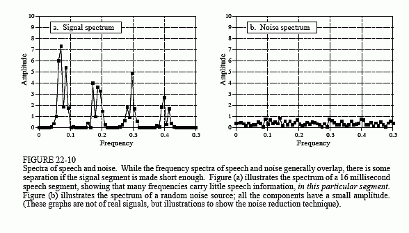
Here's how it is done. In a short segment of speech, the amplitude of the frequency components are greatly unequal. As an example, Fig. 22-10a illustrates the frequency spectrum of a 16 millisecond segment of speech (i.e., 128 samples at an 8 kHz sampling rate). Most of the signal is contained in a few large amplitude frequencies. In contrast, (b) illustrates the spectrum when only random noise is present; it is very irregular, but more uniformly distributed at a low amplitude.
Now the key concept: if both signal and noise are present, the two can be partially separated by looking at the amplitude of each frequency. If the amplitude is large, it is probably mostly signal, and should therefore be retained. If the amplitude is small, it can be attributed to mostly noise, and should therefore be discarded, i.e., set to zero. Mid-size frequency components are adjusted in some smooth manner between the two extremes.
Another way to view this technique is as a time varying Wiener filter. As you recall, the frequency response of the Wiener filter passes frequencies that are mostly signal, and rejects frequencies that are mostly noise. This

requires a knowledge of the signal and noise spectra beforehand, so that the filter's frequency response can be determined. This nonlinear technique uses the same idea, except that the Wiener filter's frequency response is recalculated for each segment, based on the spectrum of that segment. In other words, the filter's frequency response changes from segment-to-segment, as determined by the characteristics of the signal itself.
One of the difficulties in implementing this (and other) nonlinear techniques is that the overlap-add method for filtering long signals is not valid. Since the frequency response changes, the time domain waveform of each segment will no longer align with the neighboring segments. This can be overcome by remembering that audio information is encoded in frequency patterns that change over time, and not in the shape of the time domain waveform. A typical approach is to divide the original time domain signal into overlapping segments. After processing, a smooth window is applied to each of the over-lapping segments before they are recombined. This provides a smooth transition of the frequency spectrum from one segment to the next.
The second nonlinear technique is called homomorphic signal processing. This term literally means: the same structure. Addition is not the only way that noise and interference can be combined with a signal of interest; multiplication and convolution are also common means of mixing signals together. If signals are combined in a nonlinear way (i.e., anything other than addition), they cannot be separated by linear filtering. Homomorphic techniques attempt to separate signals combined in a nonlinear way by making the problem become linear. That is, the problem is converted to the same structure as a linear system.
For example, consider an audio signal transmitted via an AM radio wave. As atmospheric conditions change, the received amplitude of the signal increases and decreases, resulting in the loudness of the received audio signal slowly changing over time. This can be modeled as the audio signal, represented by , being multiplied by a slowly varying signal, , that represents the changing gain. This problem is usually handled in an electronic circuit called an automatic gain control (AGC), but it can also be corrected with nonlinear DSP.
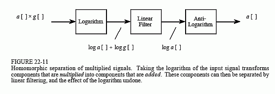
As shown in Fig. 22-11, the input signal, a[ ] × g[ ], is passed through the logarithm function. From the identity, log(xy) = log x + log y, this results in two signals that are combined by addition, i.e., log a[ ] + log g[ ]. In other words, the logarithm is the homomorphic transform that turns the nonlinear problem of multiplication into the linear problem of addition.
Next, the added signals are separated by a conventional linear filter, that is, some frequencies are passed, while others are rejected. For the AGC, the gain signal, g[ ], will be composed of very low frequencies, far below the 200 hertz to 3.2 kHz band of the voice signal. The logarithm of these signals will have more complicated spectra, but the idea is the same: a high-pass filter is used to eliminate the varying gain component from the signal.

In effect, log a[ ] + log g[ ] is converted into log a[ ]. In the last step, the logarithm is undone by using the exponential function (the anti-logarithm, or ex), producing the desired output signal, a[ ].
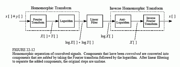
Figure 22-12 shows a homomorphic system for separating signals that have been convolved. An application where this has proven useful is in removing echoes from audio signals. That is, the audio signal is convolved with an impulse response consisting of a delta function plus a shifted and scaled delta function. The homomorphic transform for convolution is composed of two stages, the Fourier transform, changing the convolution into a multi-plication, followed by the logarithm, turning the multiplication into an addition. As before, the signals are then separated by linear filtering, and the homomorphic transform undone.
An interesting twist in Fig. 22-12 is that the linear filtering is dealing with frequency domain signals in the same way that time domain signals are usually processed. In other words, the time and frequency domains have been swapped from their normal use. For example, if FFT convolution were used to carry out the linear filtering stage, the "spectra" being multiplied would be in the time domain. This role reversal has given birth to a strange jargon. For instance, cepstrum (a rearrangment of spectrum) is the Fourier transform of the logarithm of the Fourier transform. Likewise, there are long-pass and short-pass filters, rather than low-pass and high-pass filters. Some authors even use Quefrency Alanysis and liftering.

Keep in mind that these are simplified descriptions of sophisticated DSP algorithms; homomorphic processing is filled with subtle details. For example, the logarithm must be able to handle both negative and positive values in the input signal, since this is a characteristic of audio signals. This requires the use of the complex logarithm, a more advanced concept than the logarithm used in everyday science and engineering. When the linear filtering is restricted to be a zero phase filter, the complex log is found by taking the simple logarithm of the absolute value of the signal. After passing through the zero phase filter, the sign of the original signal is reapplied to the filtered signal.
Another problem is aliasing that occurs when the logarithm is taken. For example, imagine digitizing a continuous sine wave. In accordance with the sampling theorem, two or more samples per cycle is sufficient. Now consider digitizing the logarithm of this continuous sine wave. The sharp corners require many more samples per cycle to capture the waveform, i.e., to prevent aliasing. The required sampling rate can easily be 100 times as great after the log, as before. Further, it doesn't matter if the logarithm is applied to the continuous signal, or to its digital representation; the result is the same. Aliasing will result unless the sampling rate is high enough to capture the sharp corners produced by the nonlinearity. The result is that audio signals may need to be sampled at 100 kHz or more, instead of only the standard 8 kHz.
Even if these details are handled, there is no guarantee that the linearized signals can be separated by the linear filter. This is because the spectra of the linearized signals can overlap, even if the spectra of the original signals do not. For instance, imagine adding two sine waves, one at 1 kHz, and one at 2 kHz. Since these signals do not overlap in the frequency domain, they can be completely separated by linear filtering. Now imagine that these two sine waves are multiplied. Using homomorphic processing, the log is taken of the combined signal, resulting in the log of one sine wave plus the log of the other sine wave. The problem is, the logarithm of a sine wave contains many harmonics. Since the harmonics from the two signals overlap, their complete separation is not possible.
In spite of these obstacles, homomorphic processing teaches an important lesson: signals should be processed in a manner consistent with how they are formed. Put another way, the first step in any DSP task is to understand how information is represented in the signals being process.
