The Scientist and Engineer's Guide to
Digital Signal Processing
By Steven W. Smith, Ph.D.
Book Search
Table of contents
- 1: The Breadth and Depth of DSP
- 2: Statistics, Probability and Noise
- 3: ADC and DAC
- 4: DSP Software
- 5: Linear Systems
- 6: Convolution
- 7: Properties of Convolution
- 8: The Discrete Fourier Transform
- 9: Applications of the DFT
- 10: Fourier Transform Properties
- 11: Fourier Transform Pairs
- 12: The Fast Fourier Transform
- 13: Continuous Signal Processing
- 14: Introduction to Digital Filters
- 15: Moving Average Filters
- 16: Windowed-Sinc Filters
- 17: Custom Filters
- 18: FFT Convolution
- 19: Recursive Filters
- 20: Chebyshev Filters
- 21: Filter Comparison
- 22: Audio Processing
- 23: Image Formation & Display
- 24: Linear Image Processing
- 25: Special Imaging Techniques
- 26: Neural Networks (and more!)
- 27: Data Compression
- 28: Digital Signal Processors
- 29: Getting Started with DSPs
- 30: Complex Numbers
- 31: The Complex Fourier Transform
- 32: The Laplace Transform
- 33: The z-Transform
- 34: Explaining Benford's Law
How to order your own hardcover copy
Wouldn't you rather have a bound book instead of 640 loose pages?Your laser printer will thank you!
Order from Amazon.com.
Chapter 11: Fourier Transform Pairs
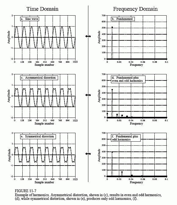
If a signal is periodic with frequency f, the only frequencies composing the signal are integer multiples of f, i.e., f, 2f, 3f, 4f, etc. These frequencies are called harmonics. The first harmonic is f, the second harmonic is 2f, the third harmonic is 3f, and so forth. The first harmonic (i.e., f) is also given a special name, the fundamental frequency. Figure 11-7 shows an


example. Figure (a) is a pure sine wave, and (b) is its DFT, a single peak. In (c), the sine wave has been distorted by poking in the tops of the peaks. Figure (d) shows the result of this distortion in the frequency domain. Because the distorted signal is periodic with the same frequency as the original sine wave, the frequency domain is composed of the original peak plus harmonics. Harmonics can be of any amplitude; however, they usually become smaller as they increase in frequency. As with any signal, sharp edges result in higher frequencies. For example, consider a common TTL logic gate generating a 1 kHz square wave. The edges rise in a few nanoseconds, resulting in harmonics being generated to nearly 100 MHz, the ten-thousandth harmonic!
Figure (e) demonstrates a subtlety of harmonic analysis. If the signal is symmetrical around a horizontal axis, i.e., the top lobes are mirror images of the bottom lobes, all of the even harmonics will have a value of zero. As shown in (f), the only frequencies contained in the signal are the fundamental, the third harmonic, the fifth harmonic, etc.
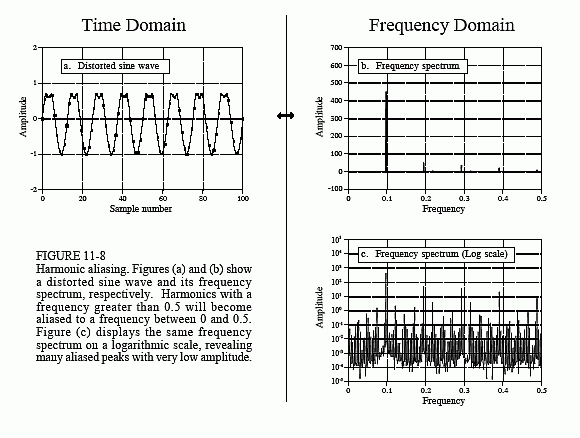
All continuous periodic signals can be represented as a summation of harmonics, just as described. Discrete periodic signals have a problem that disrupts this simple relation. As you might have guessed, the problem is aliasing. Figure 11-8a shows a sine wave distorted in the same manner as before, by poking in the tops of the peaks. This waveform looks much less regular and smooth than in the previous example because the sine wave is at a much higher frequency, resulting in fewer samples per cycle. Figure (b) shows the frequency spectrum of this signal. As you would expect, you can identify the fundamental and harmonics. This example shows that harmonics can extend to frequencies greater than 0.5 of the sampling frequency, and will be aliased to frequencies somewhere between 0 and 0.5. You don't notice them in (b) because their amplitudes are too low. Figure (c) shows the frequency spectrum plotted on a logarithmic scale to reveal these low amplitude aliased peaks. At first glance, this spectrum looks like random noise. It isn't; this is a result of the many harmonics overlapping as they are aliased.
It is important to understand that this example involves distorting a signal after it has been digitally represented. If this distortion occurred in an analog signal, you would remove the offending harmonics with an antialias filter before digitization. Harmonic aliasing is only a problem when nonlinear operations are performed directly on a discrete signal. Even then, the amplitude of these aliased harmonics is often low enough that they can be ignored.
The concept of harmonics is also useful for another reason: it explains why the DFT views the time and frequency domains as periodic. In the frequency domain, an N point DFT consists of N/2+1 equally spaced frequencies. You can view the frequencies between these samples as (1) having a value of zero, or (2) not existing. Either way they don't contribute to the synthesis of the time domain signal. In other words, a discrete frequency spectrum consists of harmonics, rather than a continuous range of frequencies. This requires the time domain to be periodic with a frequency equal to the lowest sinusoid in the frequency domain, i.e., the fundamental frequency. Neglecting the DC value, the lowest frequency represented in the frequency domain makes one complete cycle every N samples, resulting in the time domain being periodic with a period of N. In other words, if one domain is discrete, the other domain must be periodic, and vice versa. This holds for all four members of the Fourier transform family. Since the DFT views both domains as discrete, it must also view both domains as periodic. The samples in each domain represent harmonics of the periodicity of the opposite domain.
