The Scientist and Engineer's Guide to
Digital Signal Processing
By Steven W. Smith, Ph.D.
Book Search
Table of contents
- 1: The Breadth and Depth of DSP
- 2: Statistics, Probability and Noise
- 3: ADC and DAC
- 4: DSP Software
- 5: Linear Systems
- 6: Convolution
- 7: Properties of Convolution
- 8: The Discrete Fourier Transform
- 9: Applications of the DFT
- 10: Fourier Transform Properties
- 11: Fourier Transform Pairs
- 12: The Fast Fourier Transform
- 13: Continuous Signal Processing
- 14: Introduction to Digital Filters
- 15: Moving Average Filters
- 16: Windowed-Sinc Filters
- 17: Custom Filters
- 18: FFT Convolution
- 19: Recursive Filters
- 20: Chebyshev Filters
- 21: Filter Comparison
- 22: Audio Processing
- 23: Image Formation & Display
- 24: Linear Image Processing
- 25: Special Imaging Techniques
- 26: Neural Networks (and more!)
- 27: Data Compression
- 28: Digital Signal Processors
- 29: Getting Started with DSPs
- 30: Complex Numbers
- 31: The Complex Fourier Transform
- 32: The Laplace Transform
- 33: The z-Transform
- 34: Explaining Benford's Law
How to order your own hardcover copy
Wouldn't you rather have a bound book instead of 640 loose pages?Your laser printer will thank you!
Order from Amazon.com.
Chapter 29: Getting Started with DSPs
After you experiment with the prewritten programs for awhile, you will want to modify them to gain experience with the programming. Programs can be written in either assembly or C; the EZ-KIT Lite provides software tools to support both languages. Later in this chapter we will look at advanced methods of programming, such as simulation, debugging, and working in an integrated development environment. For now, we will focus on the easiest way to get a program to run. Little steps for little feet.

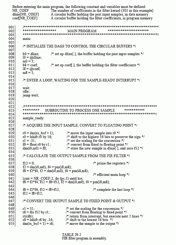
Since the source code is in ASCII, a standard text editor is all that is needed to make changes to existing files, or create entirely new programs. Table 29-2 shows an example of an FIR filter program written in assembly. While this is the only code you need to worry about for now, keep in mind that there are other files needed to make this a complete program. This includes an "architecture description file" (which defines the hardware configuration and memory allocation), setup of the interrupt vector table, and a codec initialization routine. Eventually you will need to understand what goes on in these sections, but for now you simply copy them from the prewritten programs.
As shown at the top of Table 29-2, there are three variables that need to be defined before jumping into the main section of code. These are the number of points in the filter kernel, NR_COEF; a circular buffer that holds the past samples from the input signal, dline[ ]; and a circular buffer that holds the filter kernel, coef[ ]. We also need to give the program two other pieces of information: the sampling rate of the codec, and the name of the file containing the filter kernel, so that it can be read into coef[ ]. All these steps are easy; nothing more than a single line of code each. We don't show them in this example because they are contained in the sections of code that we are ignoring for simplicity.
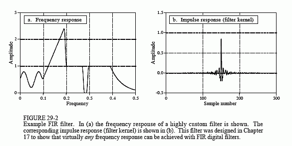
Figure 29-2 shows the filter kernel we will test the program with, the same custom filter we designed in Chapter 17. As you recall, this filter was chosen to have a very irregular frequency response, reinforcing the notion that FIR digital filters can provide virtually any frequency response you desire. Figure (a) shows the frequency response of our test filter, while (b) shows the corresponding impulse response (i.e., the filter kernel). This 301 point filter kernel is stored in an ASCII file, and is combined with the other sections of code during linking to form a single executable program.
The main section of the program performs two functions. In lines 6 to 13, the data-address-generators (DAGs) are configured to manage the circular buffers: dline[ ], and coef[ ]. As described in the last chapter, three parameters are needed for each buffer: the starting location of the buffer in memory (b0 and b8), the length of the buffer (l0 and l8), and the step size of the data being stored in the buffer (m0 and m8). These parameters that control the circular buffers are stored in hardware registers in the DAGs, allowing them to access and manage the data very efficiently.
The second action of the main program is a "thumb-twiddling" loop, implemented in lines 15 to 19. This does nothing but wait for an interrupt indicating that an input sample has been acquired. All of the processing in this program occurs on a sample-by-sample basis. Each time a sample is read from the input, a sample in the output signal is calculated and routed to the codec. Most time-domain algorithms, such as FIR and IIR filters, fall into this category. The alternative is frame-by-frame processing, which is required for frequency-domain techniques. In the frame-by-frame method, a group of samples is read from the input, calculations are conducted, and a group of samples is written to the output.
The subroutine that services the sample-ready interrupt is broken into three sections. The first section (lines 27 to 33) fetches the sample from the codec as a fixed point number, and converts it to floating point. In SHARC assembly language, a data register holding a fixed point number is referred to by "r" (such as r0, r8, r15, etc.), and by "f" if it is holding a floating point number (i.e., f0, f8, or f15.). For instance, in line 32, the fixed point number in data register 0 (i.e., r0) is converted into a floating point number and overwrites data register 0 (i.e., f0). This conversion is done according to a scaling specified by the fixed point number in data register 1 (i.e. r1). In the third section (lines 47 to 53), the opposite steps take place; the floating point number for the output sample is converted to fixed point and sent to the codec.
The FIR filter that converts the input samples into the output samples is contained in lines 35 to 45. All the calculations are carried out in floating point, avoiding the need to worry about scaling and overflow. As described in the last chapter, this section of code is optimized to take advantage of the SHARC DSP's ability to execute multiple instructions each clock cycle.
After we have the assembly program written and the filter kernel designed, we are ready to create a program that can be executed on the SHARC DSP. This is done by running the compiler, the assembler, and then the linker; three programs provided with the EZ-KIT Lite. The compiler converts a C program into the SHARC's assembly language. If you directly write the program in assembly, such as in this example, you bypass this step. The assembler and linker convert the program and external files (such as the architecture file, codec initialization routines, filter kernel, etc.) into the final executable file. All this takes about 30 seconds, with the final result being a SHARC program residing on the harddisk of your PC. The EZ-KIT Lite host is then used to run the program on the EZ-KIT Lite. Simply click

on the file you want the DSP to run, and the EZ-KIT Lite host takes care of the rest, downloading the program and starting it running.
This brings us to two questions. First, how do we test our audio filter to make sure it is operating as we designed it; and second, what in the world is a company called Analog Devices doing making Digital Signal Processors?
