The Scientist and Engineer's Guide to
Digital Signal Processing
By Steven W. Smith, Ph.D.
Book Search

Table of contents
- 1: The Breadth and Depth of DSP
- 2: Statistics, Probability and Noise
- 3: ADC and DAC
- 4: DSP Software
- 5: Linear Systems
- 6: Convolution
- 7: Properties of Convolution
- 8: The Discrete Fourier Transform
- 9: Applications of the DFT
- 10: Fourier Transform Properties
- 11: Fourier Transform Pairs
- 12: The Fast Fourier Transform
- 13: Continuous Signal Processing
- 14: Introduction to Digital Filters
- 15: Moving Average Filters
- 16: Windowed-Sinc Filters
- 17: Custom Filters
- 18: FFT Convolution
- 19: Recursive Filters
- 20: Chebyshev Filters
- 21: Filter Comparison
- 22: Audio Processing
- 23: Image Formation & Display
- 24: Linear Image Processing
- 25: Special Imaging Techniques
- 26: Neural Networks (and more!)
- 27: Data Compression
- 28: Digital Signal Processors
- 29: Getting Started with DSPs
- 30: Complex Numbers
- 31: The Complex Fourier Transform
- 32: The Laplace Transform
- 33: The z-Transform
- 34: Explaining Benford's Law
How to order your own hardcover copy
Wouldn't you rather have a bound book instead of 640 loose pages?Your laser printer will thank you!
Order from Amazon.com.
Chapter 23: Image Formation & Display
The structure and operation of the eye is very similar to an electronic camera, and it is natural to discuss them together. Both are based on two major components: a lens assembly, and an imaging sensor. The lens assembly captures a portion of the light emanating from an object, and focus it onto the imaging sensor. The imaging sensor then transforms the pattern of light into a video signal, either electronic or neural.
Figure 23-2 shows the operation of the lens. In this example, the image of an ice skater is focused onto a screen. The term focus means there is a one-to-one match of every point on the ice skater with a corresponding point on the screen. For example, consider a 1 mm ? 1 mm region on the tip of the toe. In bright light, there are roughly 100 trillion photons of light striking this one square millimeter area each second. Depending on the characteristics of the surface, between 1 and 99 percent of these incident light photons will be reflected in random directions. Only a small portion of these reflected photons will pass through the lens. For example, only about one-millionth of the reflected light will pass through a one centimeter diameter lens located 3 meters from the object.
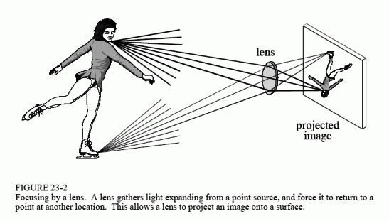
Refraction in the lens changes the direction of the individual photons, depending on the location and angle they strike the glass/air interface. These direction changes cause light expanding from a single point to return to a single point on the projection screen. All of the photons that reflect from the toe and pass through the lens are brought back together at the "toe" in the projected image. In a similar way, a portion of the light coming from any point on the object will pass through the lens, and be focused to a corresponding point in the projected image.
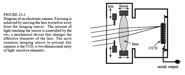
Figures 23-3 and 23-4 illustrate the major structures in an electronic camera and the human eye, respectively. Both are light tight enclosures with a lens mounted at one end and an image sensor at the other. The camera is filled with air, while the eye is filled with a transparent liquid. Each lens system has two adjustable parameters: focus and iris diameter.
If the lens is not properly focused, each point on the object will project to a circular region on the imaging sensor, causing the image to be blurry. In the camera, focusing is achieved by physically moving the lens toward or away from the imaging sensor. In comparison, the eye contains two lenses, a bulge on the front of the eyeball called the cornea, and an adjustable lens inside the eye. The cornea does most of the light refraction, but is fixed in shape and location. Adjustment to the focusing is accomplished by the inner lens, a flexible structure that can be deformed by the action of the ciliary muscles. As these muscles contract, the lens flattens to bring the object into a sharp focus.
In both systems, the iris is used to control how much of the lens is exposed to light, and therefore the brightness of the image projected onto the imaging sensor. The iris of the eye is formed from opaque muscle tissue that can be contracted to make the pupil (the light opening) larger. The iris in a camera is a mechanical assembly that performs the same function.
The parameters in optical systems interact in many unexpected ways. For example, consider how the amount of available light and the sensitivity of the light sensor affects the sharpness of the acquired image. This is because the iris diameter and the exposure time are adjusted to transfer the proper amount of light from the scene being viewed to the image sensor. If more than enough light is available, the diameter of the iris can be reduced, resulting in a greater depth-of-field (the range of distance from the camera where an object remains in focus). A greater depth-of-field provides a sharper image when objects are at various distances. In addition, an abundance of light allows the exposure time to be reduced, resulting in less blur from camera shaking and object motion. Optical systems are full of these kinds of trade-offs.
An adjustable iris is necessary in both the camera and eye because the range of light intensities in the environment is much larger than can be directly handled by the light sensors. For example, the difference in light intensities between sunlight and moonlight is about one-million. Adding to this that reflectance can vary between 1% and 99%, results in a light intensity range of almost one-hundred million.
The dynamic range of an electronic camera is typically 300 to 1000, defined as the largest signal that can be measured, divided by the inherent noise of the device. Put another way, the maximum signal produced is 1 volt, and the rms noise in the dark is about 1 millivolt. Typical camera lenses have an iris that change the area of the light opening by a factor of about 300. This results in a typical electronic camera having a dynamic range of a few hundred thousand. Clearly, the same camera and lens assembly used in bright sunlight will be useless on a dark night.
In comparison, the eye operates over a dynamic range that nearly covers the large environmental variations. Surprisingly, the iris is not the main way that this tremendous dynamic range is achieved. From dark to light, the area of the pupil only changes by a factor of about 20. The light detecting nerve cells gradually adjust their sensitivity to handle the remaining dynamic range. For instance, it takes several minutes for your eyes to adjust to the low light after walking into a dark movie theater.
One way that DSP can improve images is by reducing the dynamic range an observer is required to view. That is, we do not want very light and very dark areas in the same image. A reflection image is formed from two image signals: the two-dimensional pattern of how the scene is illuminated, multiplied by the two-dimensional pattern of reflectance in the scene. The pattern of reflectance has a dynamic range of less than 100, because all ordinary materials reflect between 1% and 99% of the incident light. This is where most of the image information is contained, such as where objects are located in the scene and what their surface characteristics are. In comparison, the illumination signal depends on the light sources around the objects, but not on the objects themselves. The illumination signal can have a dynamic range of millions, although 10 to 100 is more typical within a single image. The illumination signal carries little interesting information,
but can degrade the final image by increasing its dynamic range. DSP can improve this situation by suppressing the illumination signal, allowing the reflectance signal to dominate the image. The next chapter presents an approach for implementing this algorithm.
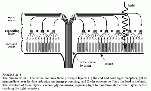
The light sensitive surface that covers the rear of the eye is called the retina. As shown in Fig. 23-5, the retina can be divided into three main layers of specialized nerve cells: one for converting light into neural signals, one for image processing, and one for transferring information to the optic nerve leading to the brain. In nearly all animals, these layers are seemingly backward. That is, the light sensitive cells are in last layer, requiring light to pass through the other layers before being detected.
There are two types of cells that detect light: rods and cones, named for their physical appearance under the microscope. The rods are specialized in operating with very little light, such as under the nighttime sky. Vision appears very noisy in near darkness, that is, the image appears to be filled with a continually changing grainy pattern. This results from the image signal being very weak, and is not a limitation of the eye. There is so little light entering the eye, the random detection of individual photons can be seen. This is called statistical noise, and is encountered in all low-light imaging, such as military night vision systems. Chapter 25 will revisit this topic. Since rods cannot detect color, low-light vision is in black and white.
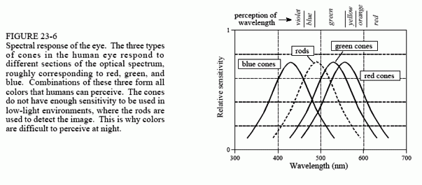
The cone receptors are specialized in distinguishing color, but can only operate when a reasonable amount of light is present. There are three types of cones in the eye: red sensitive, green sensitive, and blue sensitive. This results from their containing different photopigments, chemicals that absorbs different wavelengths (colors) of light. Figure 23-6 shows the wavelengths of light that trigger each of these three receptors. This is called RGB encoding, and is how color information leaves the eye through the optic nerve. The human perception of color is made more complicated by neural processing in the lower levels of the brain. The RGB encoding is converted into another encoding scheme, where colors are classified as: red or green, blue or yellow, and light or dark.
RGB encoding is an important limitation of human vision; the wavelengths that exist in the environment are lumped into only three broad categories. In comparison, specialized cameras can separate the optical spectrum into hundreds or thousands of individual colors. For example, these might be used to classify cells as cancerous or healthy, understand the physics of a distant star, or see camouflaged soldiers hiding in a forest. Why is the eye so limited in detecting color? Apparently, all humans need for survival is to find a red apple, among the green leaves, silhouetted against the blue sky.
Rods and cones are roughly 3 μm wide, and are closely packed over the entire 3 cm by 3 cm surface of the retina. This results in the retina being composed of an array of roughly 10,000 ? 10,000 = 100 million receptors. In comparison, the optic nerve only has about one-million nerve fibers that connect to these cells. On the average, each optic nerve fiber is connected to roughly 100 light receptors through the connecting layer. In addition to consolidating information, the connecting layer enhances the image by sharpening edges and suppressing the illumination component of the scene. This biological image processing will be discussed in the next chapter.
Directly in the center of the retina is a small region called the fovea (Latin for pit), which is used for high resolution vision (see Fig. 23-4). The fovea is different from the remainder of the retina in several respects. First, the optic nerve and interconnecting layers are pushed to the side of the fovea, allowing the receptors to be more directly exposed to the incoming light. This results in the fovea appearing as a small depression in the retina. Second, only cones are located in the fovea, and they are more tightly packed that in the remainder of the retina. This absence of rods in the fovea explains why night vision is often better when looking to the side of an object, rather than directly at it. Third, each optic nerve fiber is influenced by only a few cones, proving good localization ability. The fovea is surprisingly small. At normal reading distance, the fovea only sees about a 1 mm diameter area, less than the size of a single letter! The resolution is equivalent to about a 20?20 grid of pixels within this region.
Human vision overcomes the small size of the fovea by jerky eye movements called saccades. These abrupt motions allow the high resolution fovea to rapidly scan the field of vision for pertinent information. In addition, saccades present the rods and cones with a continually changing pattern of light. This is important because of the natural ability of the retina to adapt to changing levels of light intensity. In fact, if the eye is forced to remain fixed on the same scene, detail and color begin to fade in a few seconds.
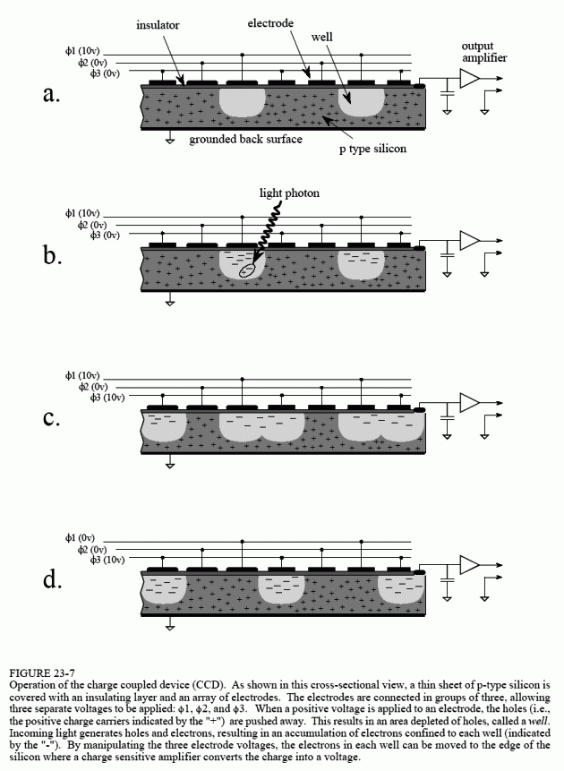
The most common image sensor used in electronic cameras is the charge coupled device (CCD). The CCD is an integrated circuit that replaced most vacuum tube cameras in the 1980s, just as transistors replaced vacuum tube amplifiers twenty years before. The heart of the CCD is a thin wafer of
silicon, typically about 1 cm square. As shown by the cross-sectional view in Fig. 23-7, the backside is coated with a thin layer of metal connected to ground potential. The topside is covered with a thin electrical insulator, and a repetitive pattern of electrodes. The most common type of CCD is the three phase readout, where every third electrode is connected together. The silicon used is called p-type, meaning it has an excess of positive charge carriers called holes. For this discussion, a hole can be thought of as a positively charged particle that is free to move around in the silicon. Holes are represented in this figure by the "+" symbol.
In (a), +10 volts is applied to one of the three phases, while the other two are held at 0 volts. This causes the holes to move away from every third electrode, since positive charges are repelled by a positive voltage. This forms a region under these electrodes called a well, a shortened version of the physics term: potential well.
Each well in the CCD is a very efficient light sensor. As shown in (b), a single photon of light striking the silicon converts its energy into the formation of two charged particles, one electron, and one hole. The hole moves away, leaving the electron stuck in the well, held by the positive voltage on the electrode. Electrons in this illustration are represented by the "-" symbol. During the integration period, the pattern of light striking the CCD is transferred into a pattern of charge within the CCD wells. Dimmer light sources require longer integration periods. For example, the integration period for standard television is 1/60th of a second, while astrophotography can accumulate light for many hours.
Readout of the electronic image is quite clever; the accumulated electrons in each well are pushed to the output amplifier. As shown in (c), a positive voltage is placed on two of the phase lines. This results in each well expanding to the right. As shown in (d), the next step is to remove the voltage from the first phase, causing the original wells to collapse. This leaves the accumulated electrons in one well to the right of where they started. By repeating this pulsing sequence among the three phase lines, the accumulated electrons are pushed to the right until they reach a charge sensitive amplifier. This is a fancy name for a capacitor followed by a unity gain buffer. As the electrons are pushed from the last well, they flow onto the capacitor where they produce a voltage. To achieve high sensitivity, the capacitors are made extremely small, usually less than 1 ρF. This capacitor and amplifier are an integral part of the CCD, and are made on the same piece of silicon. The signal leaving the CCD is a sequence of voltage levels proportional to the amount of light that has fallen on sequential wells.
Figure 23-8 shows how the two-dimensional image is read from the CCD. After the integration period, the charge accumulated in each well is moved up the column, one row at a time. For example, all the wells in row 15 are first moved into row 14, then row 13, then row 12, etc. Each time the rows are moved up, all the wells in row number 1 are transferred into the horizontal register. This is a group of specialized CCD wells that rapidly move the charge in a horizontal direction to the charge sensitive amplifier.
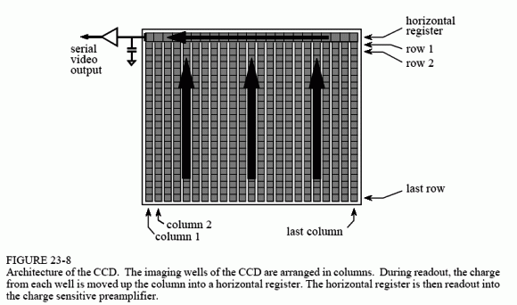
Notice that this architecture converts a two-dimensional array into a serial data stream in a particular sequence. The first pixel to be read is at the top-left corner of the image. The readout then proceeds from left-to-right on the first line, and then continues from left-to-right on subsequent lines. This is called row major order, and is almost always followed when a two-dimensional array (image) is converted to sequential data.