The Scientist and Engineer's Guide to
Digital Signal Processing
By Steven W. Smith, Ph.D.
Book Search
Table of contents
- 1: The Breadth and Depth of DSP
- 2: Statistics, Probability and Noise
- 3: ADC and DAC
- 4: DSP Software
- 5: Linear Systems
- 6: Convolution
- 7: Properties of Convolution
- 8: The Discrete Fourier Transform
- 9: Applications of the DFT
- 10: Fourier Transform Properties
- 11: Fourier Transform Pairs
- 12: The Fast Fourier Transform
- 13: Continuous Signal Processing
- 14: Introduction to Digital Filters
- 15: Moving Average Filters
- 16: Windowed-Sinc Filters
- 17: Custom Filters
- 18: FFT Convolution
- 19: Recursive Filters
- 20: Chebyshev Filters
- 21: Filter Comparison
- 22: Audio Processing
- 23: Image Formation & Display
- 24: Linear Image Processing
- 25: Special Imaging Techniques
- 26: Neural Networks (and more!)
- 27: Data Compression
- 28: Digital Signal Processors
- 29: Getting Started with DSPs
- 30: Complex Numbers
- 31: The Complex Fourier Transform
- 32: The Laplace Transform
- 33: The z-Transform
- 34: Explaining Benford's Law
How to order your own hardcover copy
Wouldn't you rather have a bound book instead of 640 loose pages?Your laser printer will thank you!
Order from Amazon.com.
Chapter 19: Recursive Filters
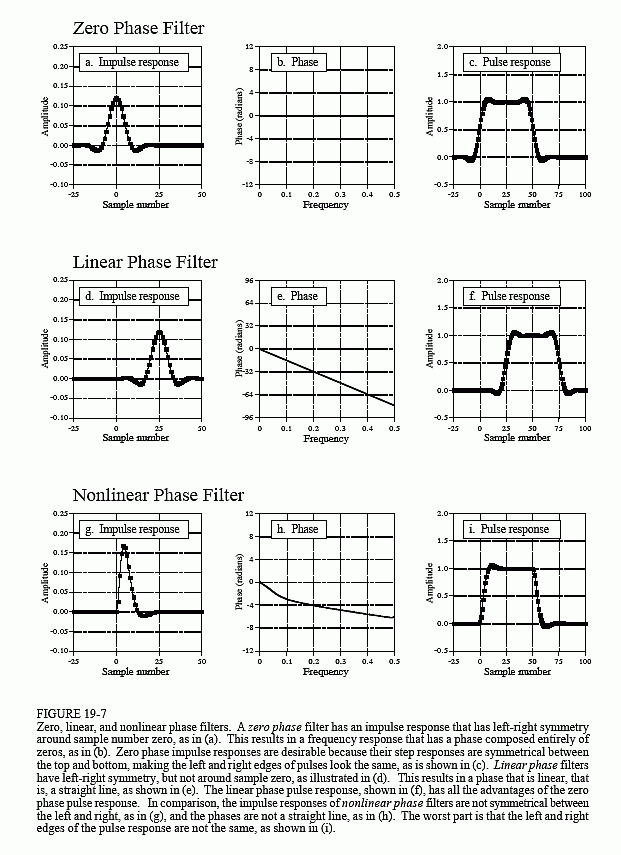
There are three types of phase response that a filter can have: zero phase, linear phase, and nonlinear phase. An example of each of these is shown in Figure 19-7. As shown in (a), the zero phase filter is characterized by an impulse response that is symmetrical around sample zero. The actual shape doesn't matter, only that the negative numbered samples are a mirror image of the positive numbered samples. When the Fourier transform is taken of this symmetrical waveform, the phase will be entirely zero, as shown in (b).
The disadvantage of the zero phase filter is that it requires the use of negative indexes, which can be inconvenient to work with. The linear phase filter is a way around this. The impulse response in (d) is identical to that shown in (a), except it has been shifted to use only positive numbered samples. The impulse response is still symmetrical between the left and right; however, the location of symmetry has been shifted from zero. This shift results in the phase, (e), being a straight line, accounting for the name: linear phase. The slope of this straight line is directly proportional to the amount of the shift. Since the shift in the impulse response does nothing but produce an identical shift in the output signal, the linear phase filter is equivalent to the zero phase filter for most purposes.
Figure (g) shows an impulse response that is not symmetrical between the left and right. Correspondingly, the phase, (h), is not a straight line. In other words, it has a nonlinear phase. Don't confuse the terms: nonlinear and linear phase with the concept of system linearity discussed in Chapter 5. Although both use the word linear, they are not related.
Why does anyone care if the phase is linear or not? Figures (c), (f), and (i) show the answer. These are the pulse responses of each of the three filters. The pulse response is nothing more than a positive going step response followed by a negative going step response. The pulse response is used here because it displays what happens to both the rising and falling edges in a signal. Here is the important part: zero and linear phase filters have left and right edges that look the same, while nonlinear phase filters have left and right edges that look different. Many applications cannot tolerate the left and right edges looking different. One example is the display of an oscilloscope, where this difference could be misinterpreted as a feature of the signal being measured. Another example is in video processing. Can you imagine turning on your TV to find the left ear of your favorite actor looking different from his right ear?
It is easy to make an FIR (finite impulse response) filter have a linear phase. This is because the impulse response (filter kernel) is directly specified in the design process. Making the filter kernel have left-right symmetry is all that is required. This is not the case with IIR (recursive) filters, since the recursion coefficients are what is specified, not the impulse response. The impulse response of a recursive filter is not symmetrical between the left and right, and therefore has a nonlinear phase.

Analog electronic circuits have this same problem with the phase response. Imagine a circuit composed of resistors and capacitors sitting on your desk. If the input has always been zero, the output will also have always been zero. When an impulse is applied to the input, the capacitors quickly charge to some value and then begin to exponentially decay through the resistors. The impulse response (i.e., the output signal) is a combination of these various decaying exponentials. The impulse response cannot be symmetrical, because the output was zero before the impulse, and the exponential decay never quite reaches a value of zero again. Analog filter designers attack this problem with the Bessel filter, presented in Chapter 3. The Bessel filter is designed to have as linear phase as possible; however, it is far below the performance of digital filters. The ability to provide an exact linear phase is a clear advantage of digital filters.
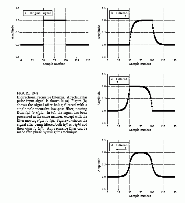
Fortunately, there is a simple way to modify recursive filters to obtain a zero phase. Figure 19-8 shows an example of how this works. The input signal to be filtered is shown in (a). Figure (b) shows the signal after it has been filtered by a single pole low-pass filter. Since this is a nonlinear phase filter, the left and right edges do not look the same; they are inverted versions of each other. As previously described, this recursive filter is implemented by starting at sample 0 and working toward sample 150, calculating each sample along the way.
Now, suppose that instead of moving from sample 0 toward sample 150, we start at sample 150 and move toward sample 0. In other words, each sample in the output signal is calculated from input and output samples to the right of the sample being worked on. This means that the recursion equation, Eq. 19-1, is changed to:

Figure (c) shows the result of this reverse filtering. This is analogous to passing an analog signal through an electronic RC circuit while running time backwards. !esrevinu eht pu-wercs nac lasrever emit -noituaC
Filtering in the reverse direction does not produce any benefit in itself; the filtered signal still has left and right edges that do not look alike. The magic happens when forward and reverse filtering are combined. Figure (d) results from filtering the signal in the forward direction and then filtering again in the reverse direction. Voila! This produces a zero phase recursive filter. In fact, any recursive filter can be converted to zero phase with this bidirectional filtering technique. The only penalty for this improved performance is a factor of two in execution time and program complexity.

How do you find the impulse and frequency responses of the overall filter? The magnitude of the frequency response is the same for each direction, while the phases are opposite in sign. When the two directions are combined, the magnitude becomes squared, while the phase cancels to zero. In the time domain, this corresponds to convolving the original impulse response with a left-for-right flipped version of itself. For instance, the impulse response of a single pole low-pass filter is a one-sided exponential. The impulse response of the corresponding bidirectional filter is a one-sided exponential that decays to the right, convolved with a one-sided exponential that decays to the left. Going through the mathematics, this turns out to be a double-sided exponential that decays both to the left and right, with the same decay constant as the original filter.
Some applications only have a portion of the signal in the computer at a particular time, such as systems that alternately input and output data on a continuing basis. Bidirectional filtering can be used in these cases by combining it with the overlap-add method described in the last chapter. When you come to the question of how long the impulse response is, don't say "infinite." If you do, you will need to pad each signal segment with an infinite number of zeros. Remember, the impulse response can be truncated when it has decayed below the round-off noise level, i.e., about 15 to 20 time constants. Each segment will need to be padded with zeros on both the left and right to allow for the expansion during the bidirectional filtering.
