The Scientist and Engineer's Guide to
Digital Signal Processing
By Steven W. Smith, Ph.D.
Book Search
Table of contents
- 1: The Breadth and Depth of DSP
- 2: Statistics, Probability and Noise
- 3: ADC and DAC
- 4: DSP Software
- 5: Linear Systems
- 6: Convolution
- 7: Properties of Convolution
- 8: The Discrete Fourier Transform
- 9: Applications of the DFT
- 10: Fourier Transform Properties
- 11: Fourier Transform Pairs
- 12: The Fast Fourier Transform
- 13: Continuous Signal Processing
- 14: Introduction to Digital Filters
- 15: Moving Average Filters
- 16: Windowed-Sinc Filters
- 17: Custom Filters
- 18: FFT Convolution
- 19: Recursive Filters
- 20: Chebyshev Filters
- 21: Filter Comparison
- 22: Audio Processing
- 23: Image Formation & Display
- 24: Linear Image Processing
- 25: Special Imaging Techniques
- 26: Neural Networks (and more!)
- 27: Data Compression
- 28: Digital Signal Processors
- 29: Getting Started with DSPs
- 30: Complex Numbers
- 31: The Complex Fourier Transform
- 32: The Laplace Transform
- 33: The z-Transform
- 34: Explaining Benford's Law
How to order your own hardcover copy
Wouldn't you rather have a bound book instead of 640 loose pages?Your laser printer will thank you!
Order from Amazon.com.
Chapter 11: Fourier Transform Pairs
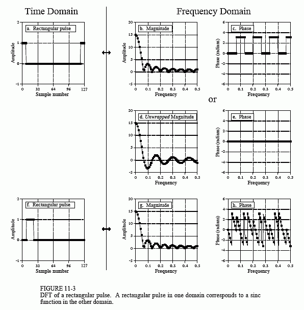
Figure 11-4 illustrates a common transform pair: the rectangular pulse and the sinc function (pronounced "sink"). The sinc function is defined as: sinc(a) = sin(πa)/(πa), however, it is common to see the vague statement: "the sinc function is of the general form: sin(x)/x." In other words, the sinc is a sine wave that decays in amplitude as 1/x. In (a), the rectangular pulse is symmetrically centered on sample zero, making one-half of the pulse on the right of the graph and the other one-half on the left. This appears to the DFT as a single pulse because of the time domain periodicity. The DFT of this signal is shown in (b) and (c), with the unwrapped version in (d) and (e).
First look at the unwrapped spectrum, (d) and (e). The unwrapped magnitude is an oscillation that decreases in amplitude with increasing frequency. The phase is composed of all zeros, as you should expect for a time domain signal that is symmetrical around sample number zero. We are using the term unwrapped magnitude to indicate that it can have both positive and negative values. By definition, the magnitude must always be positive. This is shown in (b) and (c) where the magnitude is made all positive by introducing a phase shift of π at all frequencies where the unwrapped magnitude is negative in (d).
In (f), the signal is shifted so that it appears as one contiguous pulse, but is no longer centered on sample number zero. While this doesn't change the magnitude of the frequency domain, it does add a linear component to the phase, making it a jumbled mess. What does the frequency spectrum look like as real and imaginary parts ? Too confusing to even worry about.
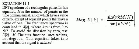
An N point time domain signal that contains a unity amplitude rectangular pulse M points wide, has a DFT frequency spectrum given by:


Alternatively, the DTFT can be used to express the frequency spectrum as a fraction of the sampling rate, f:

In other words, Eq. 11-1 provides N/2 + 1 samples in the frequency spectrum, while Eq. 11-2 provides the continuous curve that the samples lie on. These equations only provide the magnitude. The phase is determined solely by the left-right positioning of the time domain waveform, as discussed in the last chapter.
Notice in Fig. 11-3b that the amplitude of the oscillation does not decay to zero before a frequency of 0.5 is reached. As you should suspect, the waveform continues into the next period where it is aliased. This changes the shape of the frequency domain, an effect that is included in Eqs. 11-1 and 11-2.
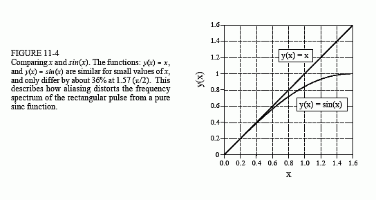
It is often important to understand what the frequency spectrum looks like when aliasing isn't present. This is because discrete signals are often used to represent or model continuous signals, and continuous signals don't alias. To remove the aliasing in Eqs. 11-1 and 11-2, change the denominators from sin(πk/N) to πk/N and from sin(πf) to πf respectively. Figure 11-4 shows the significance of this. The quantity πf can only run from 0 to 1.5708, since f can only run from 0 to 0.5. Over this range there isn't much difference between sin(πf) and πf. At zero frequency they have the same value, and at a frequency of 0.5 there is only about a 36% difference. Without aliasing, the curve in Fig. 11-3b would show a slightly lower amplitude near the right side of the graph, and no change near the left side.
When the frequency spectrum of the rectangular pulse is not aliased (because the time domain signal is continuous, or because you are ignoring the aliasing), it is of the general form: sin(x)/x, i.e., a sinc function. For continuous signals, the rectangular pulse and the sinc function are Fourier transform pairs. For discrete signals this is only an approximation, with the error being due to aliasing.
The sinc function has an annoying problem at x=0, where sin(x)/x becomes zero divided by zero. This is not a difficult mathematical problem; as x becomes very small, approaches the value of x (see Fig. 11-4).

This turns the sinc function into x/x, which has a value of one. In other words, as x becomes smaller and smaller, the value of approaches one, which includes sinc(0) = 1. Now try to tell your computer this! All it sees is a division by zero, causing it to complain and stop your program. The important point to remember is that your program must include special handling at x = 0 when calculating the sinc function.
A key trait of the sinc function is the location of the zero crossings. These occur at frequencies where an integer number of the sinusoid's cycles fit evenly into the rectangular pulse. For example, if the rectangular pulse is 20 points wide, the first zero in the frequency domain is at the frequency that makes one complete cycle in 20 points. The second zero is at the frequency that makes two complete cycles in 20 points, etc. This can be understood by remembering how the DFT is calculated by correlation. The amplitude of a frequency component is found by multiplying the time domain signal by a sinusoid and adding up the resulting samples. If the time domain waveform is a rectangular pulse of unity amplitude, this is the same as adding the sinusoid's samples that are within the rectangular pulse. If this summation occurs over an integral number of the sinusoid's cycles, the result will be zero.
The sinc function is widely used in DSP because it is the Fourier transform pair of a very simple waveform, the rectangular pulse. For example, the sinc function is used in spectral analysis, as discussed in Chapter 9. Consider the analysis of an infinitely long discrete signal. Since the DFT can only work with finite length signals, N samples are selected to represent the longer signal. The key here is that "selecting N samples from a longer signal" is the same as multiplying the longer signal by a rectangular pulse. The ones in the rectangular pulse retain the corresponding samples, while the zeros eliminate them. How does this affect the frequency spectrum of the signal? Multiplying the time domain by a rectangular pulse results in the frequency domain being convolved with a sinc function. This reduces the frequency spectrum's resolution, as previously shown in Fig. 9-5a.
