The Scientist and Engineer's Guide to
Digital Signal Processing
By Steven W. Smith, Ph.D.
Book Search
Table of contents
- 1: The Breadth and Depth of DSP
- 2: Statistics, Probability and Noise
- 3: ADC and DAC
- 4: DSP Software
- 5: Linear Systems
- 6: Convolution
- 7: Properties of Convolution
- 8: The Discrete Fourier Transform
- 9: Applications of the DFT
- 10: Fourier Transform Properties
- 11: Fourier Transform Pairs
- 12: The Fast Fourier Transform
- 13: Continuous Signal Processing
- 14: Introduction to Digital Filters
- 15: Moving Average Filters
- 16: Windowed-Sinc Filters
- 17: Custom Filters
- 18: FFT Convolution
- 19: Recursive Filters
- 20: Chebyshev Filters
- 21: Filter Comparison
- 22: Audio Processing
- 23: Image Formation & Display
- 24: Linear Image Processing
- 25: Special Imaging Techniques
- 26: Neural Networks (and more!)
- 27: Data Compression
- 28: Digital Signal Processors
- 29: Getting Started with DSPs
- 30: Complex Numbers
- 31: The Complex Fourier Transform
- 32: The Laplace Transform
- 33: The z-Transform
- 34: Explaining Benford's Law
How to order your own hardcover copy
Wouldn't you rather have a bound book instead of 640 loose pages?Your laser printer will thank you!
Order from Amazon.com.
Chapter 12: The Fast Fourier Transform
There are several techniques for making the FFT even faster; however, the improvements are only about 20-40%. In one of these methods, the time
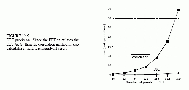
domain decomposition is stopped two stages early, when each signals is composed of only four points. Instead of calculating the last two stages, highly optimized code is used to jump directly into the frequency domain, using the simplicity of four point sine and cosine waves.
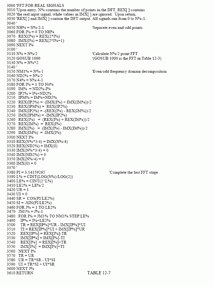
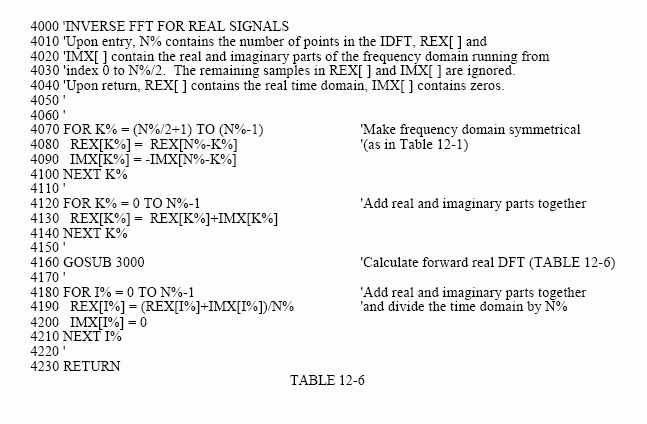
Another popular algorithm eliminates the wasted calculations associated with the imaginary part of the time domain being zero, and the frequency spectrum being symmetrical. In other words, the FFT is modified to calculate the real DFT, instead of the complex DFT. These algorithms are called the real FFT and the real Inverse FFT (or similar names). Expect them to be about 30% faster than the conventional FFT routines. Tables 12-6 and 12-7 show programs for these algorithms.
There are two small disadvantages in using the real FFT. First, the code is about twice as long. While your computer doesn't care, you must take the time to convert someone else's program to run on your computer. Second, debugging these programs is slightly harder because you cannot use symmetry as a check for proper operation. These algorithms force the imaginary part of the time domain to be zero, and the frequency domain to have left-right symmetry. For debugging, check that these programs produce the same output as the conventional FFT algorithms.
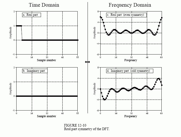
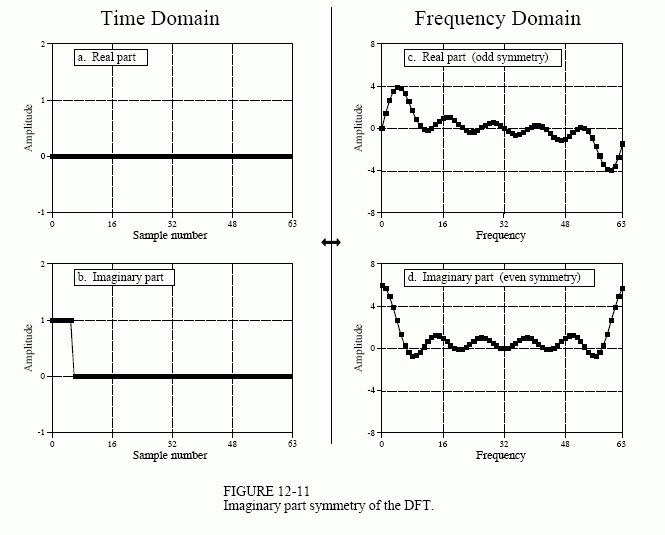
Figures 12-10 and 12-11 illustrate how the real FFT works. In Fig. 12-10, (a) and (b) show a time domain signal that consists of a pulse in the real part, and all zeros in the imaginary part. Figures (c) and (d) show the corresponding frequency spectrum. As previously described, the frequency domain's real part has an even symmetry around sample 0 and sample N/2, while the imaginary part has an odd symmetry around these same points.
Now consider Fig. 12-11, where the pulse is in the imaginary part of the time domain, and the real part is all zeros. The symmetry in the frequency domain is reversed; the real part is odd, while the imaginary part is even. This situation will be discussed in Chapter 29. For now, take it for granted that this is how the complex DFT behaves.
What if there is a signal in both parts of the time domain? By additivity, the frequency domain will be the sum of the two frequency spectra. Now the key element: a frequency spectrum composed of these two types of symmetry can be perfectly separated into the two component signals. This is achieved by the even/odd decomposition discussed in Chapter 6. In other words, two DFT's can be calculated for the price of one. One of the signals is placed in the real part of the time domain, and the other signal is placed in the imaginary part. After calculating the complex DFT (via the FFT, of course), the spectra are separated using the even/odd decomposition. When two or more signals need to be passed through the FFT, this technique reduces the execution time by about 40%. The improvement isn't a full factor of two because of the calculation time required for the even/odd decomposition. This is a relatively simple technique with few pitfalls, nothing like writing an FFT routine from scratch.
The next step is to modify the algorithm to calculate a single DFT faster. It's ugly, but here is how it is done. The input signal is broken in half by using an interlaced decomposition. The N/2 even points are placed into the real part of the time domain signal, while the N/2 odd points go into the imaginary part. An N/2 point FFT is then calculated, requiring about one-half the time as an N point FFT. The resulting frequency domain is then separated by the even/odd decomposition, resulting in the frequency spectra of the two interlaced time domain signals. These two frequency spectra are then combined into a single spectrum, just as in the last synthesis stage of the FFT.
To close this chapter, consider that the FFT is to Digital Signal Processing what the transistor is to electronics. It is a foundation of the technology; everyone in the field knows its characteristics and how to use it. However, only a small number of specialists really understand the details of the internal workings.
