The Scientist and Engineer's Guide to
Digital Signal Processing
By Steven W. Smith, Ph.D.
Book Search
Table of contents
- 1: The Breadth and Depth of DSP
- 2: Statistics, Probability and Noise
- 3: ADC and DAC
- 4: DSP Software
- 5: Linear Systems
- 6: Convolution
- 7: Properties of Convolution
- 8: The Discrete Fourier Transform
- 9: Applications of the DFT
- 10: Fourier Transform Properties
- 11: Fourier Transform Pairs
- 12: The Fast Fourier Transform
- 13: Continuous Signal Processing
- 14: Introduction to Digital Filters
- 15: Moving Average Filters
- 16: Windowed-Sinc Filters
- 17: Custom Filters
- 18: FFT Convolution
- 19: Recursive Filters
- 20: Chebyshev Filters
- 21: Filter Comparison
- 22: Audio Processing
- 23: Image Formation & Display
- 24: Linear Image Processing
- 25: Special Imaging Techniques
- 26: Neural Networks (and more!)
- 27: Data Compression
- 28: Digital Signal Processors
- 29: Getting Started with DSPs
- 30: Complex Numbers
- 31: The Complex Fourier Transform
- 32: The Laplace Transform
- 33: The z-Transform
- 34: Explaining Benford's Law
How to order your own hardcover copy
Wouldn't you rather have a bound book instead of 640 loose pages?Your laser printer will thank you!
Order from Amazon.com.
Chapter 14: Introduction to Digital Filters
High-pass, band-pass and band-reject filters are designed by starting with a low-pass filter, and then converting it into the desired response. For this reason, most discussions on filter design only give examples of low-pass filters. There are two methods for the low-pass to high-pass conversion: spectral inversion and spectral reversal. Both are equally useful.
An example of spectral inversion is shown in 14-5. Figure (a) shows a low-pass filter kernel called a windowed-sinc (the topic of Chapter 16). This filter kernel is 51 points in length, although many of samples have a value so small that they appear to be zero in this graph. The corresponding

frequency response is shown in (b), found by adding 13 zeros to the filter kernel and taking a 64 point FFT. Two things must be done to change the low-pass filter kernel into a high-pass filter kernel. First, change the sign of each sample in the filter kernel. Second, add one to the sample at the center of symmetry. This results in the high-pass filter kernel shown in (c), with the frequency response shown in (d). Spectral inversion flips the frequency response top-for-bottom, changing the passbands into stopbands, and the stopbands into passbands. In other words, it changes a filter from low-pass to high-pass, high-pass to low-pass, band-pass to band-reject, or band-reject to band-pass.
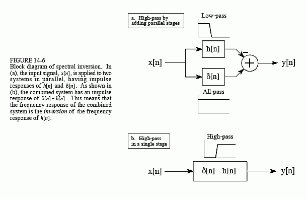
Figure 14-6 shows why this two step modification to the time domain results in an inverted frequency spectrum. In (a), the input signal, x[n], is applied to two systems in parallel. One of these systems is a low-pass filter, with an impulse response given by h[n]. The other system does nothing to the signal, and therefore has an impulse response that is a delta function, δ[n]. The overall output, y[n], is equal to the output of the all-pass system minus the output of the low-pass system. Since the low frequency components are subtracted from the original signal, only the high frequency components appear in the output. Thus, a high-pass filter is formed.
This could be performed as a two step operation in a computer program: run the signal through a low-pass filter, and then subtract the filtered signal from the original. However, the entire operation can be performed in a signal stage by combining the two filter kernels. As described in Chapter

7, parallel systems with added outputs can be combined into a single stage by adding their impulse responses. As shown in (b), the filter kernel for the high-pass filter is given by: δ[n] - h[n]. That is, change the sign of all the samples, and then add one to the sample at the center of symmetry.
For this technique to work, the low-frequency components exiting the low-pass filter must have the same phase as the low-frequency components exiting the all-pass system. Otherwise a complete subtraction cannot take place. This places two restrictions on the method: (1) the original filter kernel must have left-right symmetry (i.e., a zero or linear phase), and (2) the impulse must be added at the center of symmetry.
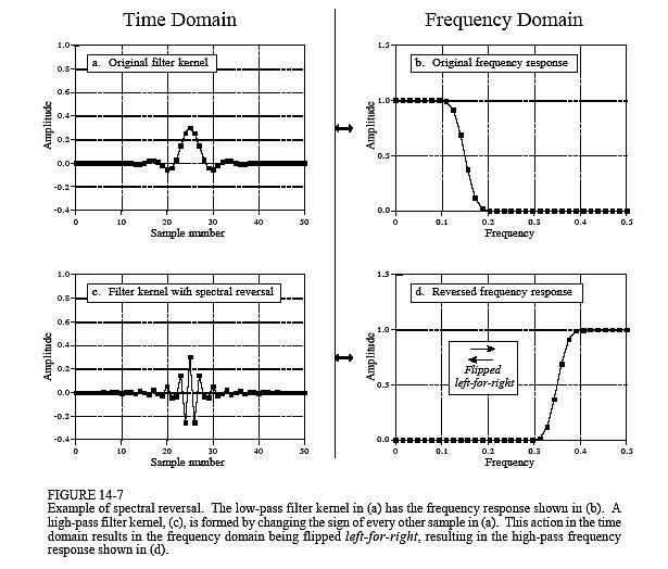
The second method for low-pass to high-pass conversion, spectral reversal, is illustrated in Fig. 14-7. Just as before, the low-pass filter kernel in (a) corresponds to the frequency response in (b). The high-pass filter kernel, (c), is formed by changing the sign of every other sample in (a). As shown in (d), this flips the frequency domain left-for-right: 0 becomes 0.5 and 0.5

becomes 0. The cutoff frequency of the example low-pass filter is 0.15, resulting in the cutoff frequency of the high-pass filter being 0.35.
Changing the sign of every other sample is equivalent to multiplying the filter kernel by a sinusoid with a frequency of 0.5. As discussed in Chapter 10, this has the effect of shifting the frequency domain by 0.5. Look at (b) and imagine the negative frequencies between -0.5 and 0 that are of mirror image of the frequencies between 0 and 0.5. The frequencies that appear in (d) are the negative frequencies from (b) shifted by 0.5.
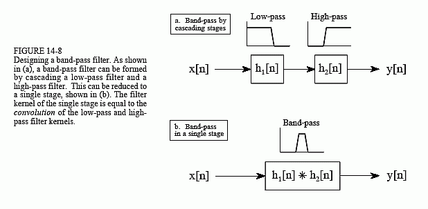
Lastly, Figs. 14-8 and 14-9 show how low-pass and high-pass filter kernels can be combined to form band-pass and band-reject filters. In short, adding the filter kernels produces a band-reject filter, while convolving the filter kernels produces a band-pass filter. These are based on the way cascaded and parallel systems are be combined, as discussed in Chapter 7. Multiple combination of these techniques can also be used. For instance, a band-pass filter can be designed by adding the two filter kernels to form a band-pass filter, and then use spectral inversion or spectral reversal as previously described. All these techniques work very well with few surprises.
