The Scientist and Engineer's Guide to
Digital Signal Processing
By Steven W. Smith, Ph.D.
Book Search
Table of contents
- 1: The Breadth and Depth of DSP
- 2: Statistics, Probability and Noise
- 3: ADC and DAC
- 4: DSP Software
- 5: Linear Systems
- 6: Convolution
- 7: Properties of Convolution
- 8: The Discrete Fourier Transform
- 9: Applications of the DFT
- 10: Fourier Transform Properties
- 11: Fourier Transform Pairs
- 12: The Fast Fourier Transform
- 13: Continuous Signal Processing
- 14: Introduction to Digital Filters
- 15: Moving Average Filters
- 16: Windowed-Sinc Filters
- 17: Custom Filters
- 18: FFT Convolution
- 19: Recursive Filters
- 20: Chebyshev Filters
- 21: Filter Comparison
- 22: Audio Processing
- 23: Image Formation & Display
- 24: Linear Image Processing
- 25: Special Imaging Techniques
- 26: Neural Networks (and more!)
- 27: Data Compression
- 28: Digital Signal Processors
- 29: Getting Started with DSPs
- 30: Complex Numbers
- 31: The Complex Fourier Transform
- 32: The Laplace Transform
- 33: The z-Transform
- 34: Explaining Benford's Law
How to order your own hardcover copy
Wouldn't you rather have a bound book instead of 640 loose pages?Your laser printer will thank you!
Order from Amazon.com.
Chapter 28: Digital Signal Processors
The primary reason for using a DSP instead of a traditional microprocessor is speed, the ability to move samples into the device, carry out the needed mathematical operations, and output the processed data. This brings up the question: How fast are DSPs? The usual way of answering this question is benchmarks, methods for expressing the speed of a microprocessor as a number. For instance, fixed point systems are often quoted in MIPS (million integer operations per second). Likewise, floating point devices can be specified in MFLOPS (million floating point operations per second).
One hundred and fifty years ago, British Prime Minister Benjamin Disraeli declared that there are three types of lies: lies, damn lies, and statistics. If Disraeli were alive today and working with microprocessors, he would add benchmarks as a fourth category. The idea behind benchmarks is to provide a head-to-head comparison to show which is the best device. Unfortunately, this often fails in practicality, because different microprocessors excel in different areas. Imagine asking the question: Which is the better car, a Cadillac or a Ferrari? It depends on what you want it for!
Confusion about benchmarks is aggravated by the competitive nature of the electronics industry. Manufacturers want to show their products in the best light, and they will use any ambiguity in the testing procedure to their advantage. There is an old saying in electronics: "A specification writer can get twice as much performance from a device as an engineer." These people aren't being untruthful, they are just paid to have good imaginations. Benchmarks should be viewed as a tool for a complicated task. If you are inexperienced in using this tool, you may come to the wrong conclusion. A better approach is to look for specific information on the execution speed of the algorithms you plan to carry out. For instance, if your application calls for an FIR filter, look for the exact number of clock cycles it takes for the device to execute this particular task.
Using this strategy, let's look at the time required to execute various algorithms on our featured DSP, the Analog Devices SHARC family. Keep

in mind that microprocessor speed is doubling about every three years. This means you should pay special attention to the method we use in this example. The actual numbers are always changing, and you will need to repeat the calculations every time you start a new project. In the world of twenty-first century technology, blink and you are out-of-date!
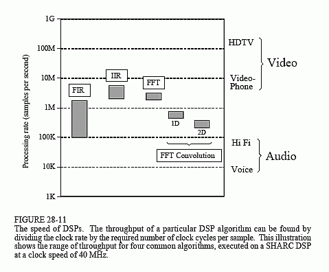
When it comes to understanding execution time, the SHARC family is one of the easiest DSP to work with. This is because it can carry out a multiply-accumulate operation in a single clock cycle. Since most FIR filters use 25 to 400 coefficients, 25 to 400 clock cycles are required, respectively, for each sample being processed. As previously described, there is a small amount of overhead needed to achieve this loop efficiency (priming the first loop and completing the last loop), but it is negligible when the number of loops is this large. To obtain the throughput of the filter, we can divide the SHARC clock rate (40 MHz at present) by the number of clock cycles required per sample. This gives us a maximum FIR data rate of about 100k to 1.6M samples/second. The calculations can't get much simpler than this! These FIR throughput values are shown in Fig. 28-11.
The calculations are just as easy for recursive filters. Typical IIR filters use about 5 to 17 coefficients. Since these loops are relatively short, we will add a small amount of overhead, say 3 cycles per sample. This results in 8 to 20 clock cycles being required per sample of processed data. For the 40 MHz clock rate, this provides a maximum IIR throughput of 1.8M to 3.1M samples/second. These IIR values are also shown in Fig. 28-11.
Next we come to the frequency domain techniques, based on the Fast Fourier Transform. FFT subroutines are almost always provided by the manufacturer of the DSP. These are highly-optimized routines written in assembly. The specification sheet of the ADSP-21062 SHARC DSP indicates that a 1024 sample complex FFT requires 18,221 clock cycles, or about 0.46 milliseconds at 40 MHz. To calculate the throughput, it is easier to view this as 17.8 clock cycles per sample. This "per-sample" value only changes slightly with longer or shorter FFTs. For instance, a 256 sample FFT requires about 14.2 clock cycles per sample, and a 4096 sample FFT requires 21.4 clock cycles per sample. Real FFTs can be calculated about 40% faster than these complex FFT values. This makes the overall range of all FFT routines about 10 to 22 clock cycles per sample, corresponding to a throughput of about 1.8M to 3.3M samples/second.
FFT convolution is a fast way to carry out FIR filters. In a typical case, a 512 sample segment is taken from the input, padded with an additional 512 zeros, and converted into its frequency spectrum by using a 1024 point FFT. After multiplying this spectrum by the desired frequency response, a 1024 point Inverse FFT is used to move back into the time domain. The resulting 1024 points are combined with the adjacent processed segments using the overlap-add method. This produces 512 points of the output signal.
How many clock cycles does this take? Each 512 sample segment requires two 1024 point FFTs, plus a small amount of overhead. In round terms, this is about a factor of five greater than for a single FFT of 512 points. Since the real FFT requires about 12 clock cycles per sample, FFT convolution can be carried out in about 60 clock cycles per sample. For a 2106x SHARC DSP at 40 MHz, this corresponds to a data throughput of approximately 660k samples/second.
Notice that this is about the same as a 60 coefficient FIR filter carried out by conventional convolution. In other words, if an FIR filter has less than 60 coefficients, it can be carried out faster by standard convolution. If it has greater than 60 coefficients, FFT convolution is quicker. A key advantage of FFT convolution is that the execution time only increases as the logarithm of the number of coefficients. For instance a 4,096 point filter kernel only requires about 30% longer to execute as one with only 512 points.
FFT convolution can also be applied in two-dimensions, such as for image processing. For instance, suppose we want to process an 800×600 pixel image in the frequency domain. First, pad the image with zeros to make it 1024×1024. The two-dimensional frequency spectrum is then calculated by taking the FFT of each of the rows, followed by taking the FFT of each of the resulting columns. After multiplying this 1024×1024 spectrum by the desired frequency response, the two-dimensional Inverse FFT is taken. This is carried out by taking the Inverse FFT of each of the rows, and then each of the resulting columns. Adding the number of clock cycles and dividing by the number of samples, we find that this entire procedure takes roughly 150 clock cycles per pixel. For a 40 MHz ADSP-2106, this corresponds to a data throughput of about 260k samples/second.
Comparing these different techniques in Fig. 28-11, we can make an important observation. Nearly all DSP techniques require between 4 and 400 instructions (clock cycles in the SHARC family) to execute. For a SHARC DSP operating at 40 MHz, we can immediately conclude that its data throughput will be between 100k and 10M samples per second, depending on how complex of algorithm is used.
Now that we understand how fast DSPs can process digitized signals, let's turn our attention to the other end; how fast do we need to process the data? Of course, this depends on the application. We will look at two of the most common, audio and video processing.
The data rate needed for an audio signal depends on the required quality of the reproduced sound. At the low end, telephone quality speech only requires capturing the frequencies between about 100 Hz and 3.2 kHz, dictating a sampling rate of about 8k samples/second. In comparison, high fidelity music must contain the full 20 Hz to 20 kHz range of human hearing. A 44.1 kHz sampling rate is often used for both the left and right channels, making the complete Hi Fi signal 88.2k samples/second. How does the SHARC family compare with these requirements? As shown in Fig. 28-11, it can easily handle high fidelity audio, or process several dozen voice signals at the same time.
Video signals are a different story; they require about one-thousand times the data rate of audio signals. A good example of low quality video is the the CIF (Common Interface Format) standard for videophones. This uses 352×288 pixels, with 3 colors per pixel, and 30 frames per second, for a total data rate of 9.1 million samples per second. At the high end of quality there is HDTV (high-definition television), using 1920×1080 pixels, with 3 colors per pixel, and 30 frames per second. This requires a data rate to over 186 million samples per second. These data rates are above the capabilities of a single SHARC DSP, as shown in Fig. 28-11. There are other applications that also require these very high data rates, for instance, radar, sonar, and military uses such as missile guidance.
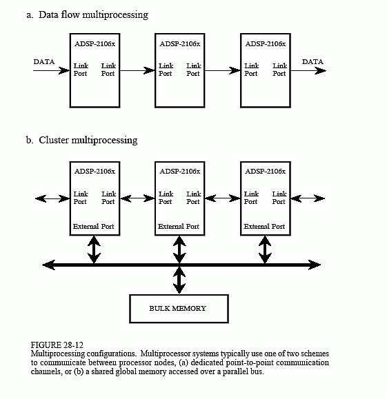
To handle these high-power tasks, several DSPs can be combined into a single system. This is called multiprocessing or parallel processing. The SHARC DSPs were designed with this type of multiprocessing in mind, and include special features to make it as easy as possible. For instance, no external hardware logic is required to connect the external busses of multiple SHARC DSPs together; all of the bus arbitration logic is already contained within each device. As an alternative, the link ports (4 bit, parallel) can be used to connect multiple processors in various configurations. Figure 28-12 shows typical ways that the SHARC DSPs can be arranged in multiprocessing systems. In Fig. (a), the algorithm is broken into sequential steps, with each processor performing one of the steps in an "assembly line"

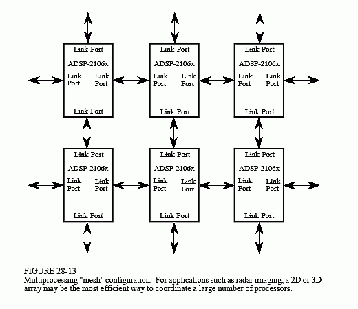
strategy. In (b), the processors interact through a single shared global memory, accessed over a parallel bus (i.e., the external port). Figure 28-13 shows another way that a large number of processors can be combined into a single system, a 2D or 3D "mesh." Each of these configuration will have relative advantages and disadvantages for a particular task.
To make the programmer's life easier, the SHARC family uses a unified address space. This means that the 4 Gigaword address space, accessed by the 32 bit address bus, is divided among the various processors that are working together. To transfer data from one processor to another, simply read from or write to the appropriate memory locations. The SHARC internal logic takes care of the rest, transferring the data between processors at a rate as high as 240 Mbytes/sec (at 40 MHz).

