The Scientist and Engineer's Guide to
Digital Signal Processing
By Steven W. Smith, Ph.D.
Book Search

Table of contents
- 1: The Breadth and Depth of DSP
- 2: Statistics, Probability and Noise
- 3: ADC and DAC
- 4: DSP Software
- 5: Linear Systems
- 6: Convolution
- 7: Properties of Convolution
- 8: The Discrete Fourier Transform
- 9: Applications of the DFT
- 10: Fourier Transform Properties
- 11: Fourier Transform Pairs
- 12: The Fast Fourier Transform
- 13: Continuous Signal Processing
- 14: Introduction to Digital Filters
- 15: Moving Average Filters
- 16: Windowed-Sinc Filters
- 17: Custom Filters
- 18: FFT Convolution
- 19: Recursive Filters
- 20: Chebyshev Filters
- 21: Filter Comparison
- 22: Audio Processing
- 23: Image Formation & Display
- 24: Linear Image Processing
- 25: Special Imaging Techniques
- 26: Neural Networks (and more!)
- 27: Data Compression
- 28: Digital Signal Processors
- 29: Getting Started with DSPs
- 30: Complex Numbers
- 31: The Complex Fourier Transform
- 32: The Laplace Transform
- 33: The z-Transform
- 34: Explaining Benford's Law
How to order your own hardcover copy
Wouldn't you rather have a bound book instead of 640 loose pages?Your laser printer will thank you!
Order from Amazon.com.
Chapter 25: Special Imaging Techniques
The identification of objects within an image can be a very difficult task. One way to simplify the problem is to change the grayscale image into a binary image, in which each pixel is restricted to a value of either 0 or 1. The techniques used on these binary images go by such names as: blob analysis, connectivity analysis, and morphological image processing (from the Greek word morphē, meaning shape or form). The foundation of morphological processing is in the mathematically rigorous field of set theory; however, this level of sophistication is seldom needed. Most morphological algorithms are simple logic operations and very ad hoc. In
other words, each application requires a custom solution developed by trial-and-error. This is usually more of an art than a science. A bag of tricks is used rather than standard algorithms and formal mathematical properties. Here are some examples.
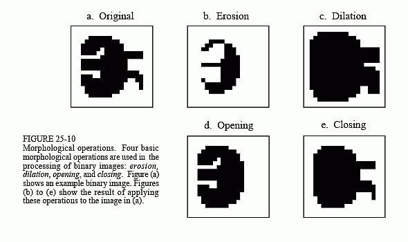
Figure 25-10a shows an example binary image. This might represent an enemy tank in an infrared image, an asteroid in a space photograph, or a suspected tumor in a medical x-ray. Each pixel in the background is displayed as white, while each pixel in the object is displayed as black. Frequently, binary images are formed by thresholding a grayscale image; pixels with a value greater than a threshold are set to 1, while pixels with a value below the threshold are set to 0. It is common for the grayscale image to be processed with linear techniques before the thresholding. For instance, illumination flattening (described in Chapter 24) can often improve the quality of the initial binary image.
Figures (b) and (c) show how the image is changed by the two most common morphological operations, erosion and dilation. In erosion, every object pixel that is touching a background pixel is changed into a background pixel. In dilation, every background pixel that is touching an object pixel is changed into an object pixel. Erosion makes the objects smaller, and can break a single object into multiple objects. Dilation makes the objects larger, and can merge multiple objects into one.
As shown in (d), opening is defined as an erosion followed by a dilation. Figure (e) shows the opposite operation of closing, defined as a dilation followed by an erosion. As illustrated by these examples, opening removes small islands and thin filaments of object pixels. Likewise, closing removes islands and thin filaments of background pixels. These techniques are useful for handling noisy images where some pixels have the wrong binary value. For instance, it might be known that an object cannot contain a "hole", or that the object's border must be smooth.
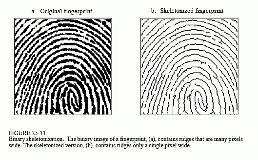
Figure 25-11 shows an example of morphological processing. Figure (a) is the binary image of a fingerprint. Algorithms have been developed to analyze these patterns, allowing individual fingerprints to be matched with those in a database. A common step in these algorithms is shown in (b), an operation called skeletonization. This simplifies the image by removing redundant pixels; that is, changing appropriate pixels from black to white. This results in each ridge being turned into a line only a single pixel wide.
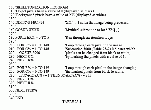
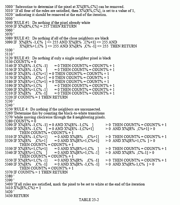
Tables 25-1 and 25-2 show the skeletonization program. Even though the fingerprint image is binary, it is held in an array where each pixel can run from 0 to 255. A black pixel is denoted by 0, while a white pixel is denoted by 255. As shown in Table 25-1, the algorithm is composed of 6 iterations that gradually erode the ridges into a thin line. The number of iterations is chosen by trial and error. An alternative would be to stop when an iteration makes no changes.
During an iteration, each pixel in the image is evaluated for being removable; the pixel meets a set of criteria for being changed from black to white. Lines 200-240 loop through each pixel in the image, while the subroutine in Table 25-2 makes the evaluation. If the pixel under consideration is not removable, the subroutine does nothing. If the pixel is removable, the subroutine changes its value from 0 to 1. This indicates that the pixel is still black, but will be changed to white at the end of the iteration. After all the pixels have been evaluated, lines 260-300 change the value of the marked pixels from 1 to 255. This two-stage process results in the thick ridges being eroded equally from all directions, rather than a pattern based on how the rows and columns are scanned.
The decision to remove a pixel is based on four rules, as contained in the subroutine shown in Table 25-2. All of these rules must be satisfied for a pixel to be changed from black to white. The first three rules are rather simple, while the fourth is quite complicated. As shown in Fig. 25-12a, a pixel at location [R,C] has eight neighbors. The four neighbors in the horizontal and vertical directions (labeled 2,4,6,8) are frequently called the close neighbors. The diagonal pixels (labeled 1,3,5,7) are correspondingly called the distant neighbors. The four rules are as follows:
Rule one: The pixel under consideration must presently be black. If the pixel is already white, no action needs to be taken.
Rule two: At least one of the pixel's close neighbors must be white. This insures that the erosion of the thick ridges takes place from the outside. In other words, if a pixel is black, and it is completely surrounded by black pixels, it is to be left alone on this iteration. Why use only the close neighbors, rather than all of the neighbors? The answer is simple: running the algorithm both ways shows that it works better. Remember, this is very common in morphological image processing; trial and error is used to find if one technique performs better than another.
Rule three: The pixel must have more than one black neighbor. If it has only one, it must be the end of a line, and therefore shouldn't be removed.
Rule four: A pixel cannot be removed if it results in its neighbors being disconnected. This is so each ridge is changed into a continuous line, not a group of interrupted segments. As shown by the examples in Fig. 25-12,
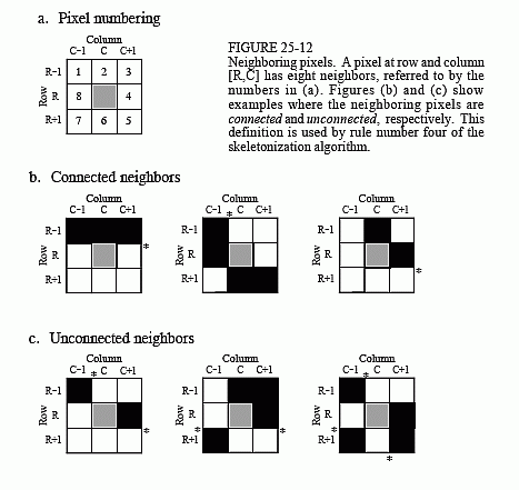
connected means that all of the black neighbors touch each other. Likewise, unconnected means that the black neighbors form two or more groups.
The algorithm for determining if the neighbors are connected or unconnected is based on counting the black-to-white transitions between adjacent neighboring pixels, in a clockwise direction. For example, if pixel 1 is black and pixel 2 is white, it is considered a black-to-white transition. Likewise, if pixel 2 is black and both pixel 3 and 4 are white, this is also a black-to-white transition. In total, there are eight locations where a black-to-white transition may occur. To illustrate this definition further, the examples in (b) and (c) have an asterisk placed by each black-to-white transition. The key to this algorithm is that there will be exactly one black-to-white transition if the neighbors are connected. More than one such transition indicates that the neighbors are unconnected.
As additional examples of binary image processing, consider the types of algorithms that might be useful after the fingerprint is skeletonized. A disadvantage of this particular skeletonization algorithm is that it leaves a considerable amount of fuzz, short offshoots that stick out from the sides of longer segments. There are several different approaches for eliminating these artifacts. For example, a program might loop through the image removing the pixel at the end of every line. These pixels are identified
by having only one black neighbor. Do this several times and the fuzz is removed at the expense of making each of the correct lines shorter. A better method would loop through the image identifying branch pixels (pixels that have more than two neighbors). Starting with each branch pixel, count the number of pixels in each offshoot. If the number of pixels in an offshoot is less than some value (say, 5), declare it to be fuzz, and change the pixels in the branch from black to white.
Another algorithm might change the data from a bitmap to a vector mapped format. This involves creating a list of the ridges contained in the image and the pixels contained in each ridge. In the vector mapped form, each ridge in the fingerprint has an individual identity, as opposed to an image composed of many unrelated pixels. This can be accomplished by looping through the image looking for the endpoints of each line, the pixels that have only one black neighbor. Starting from the endpoint, each line is traced from pixel to connecting pixel. After the opposite end of the line is reached, all the traced pixels are declared to be a single object, and treated accordingly in future algorithms.