The Scientist and Engineer's Guide to
Digital Signal Processing
By Steven W. Smith, Ph.D.
Book Search
Table of contents
- 1: The Breadth and Depth of DSP
- 2: Statistics, Probability and Noise
- 3: ADC and DAC
- 4: DSP Software
- 5: Linear Systems
- 6: Convolution
- 7: Properties of Convolution
- 8: The Discrete Fourier Transform
- 9: Applications of the DFT
- 10: Fourier Transform Properties
- 11: Fourier Transform Pairs
- 12: The Fast Fourier Transform
- 13: Continuous Signal Processing
- 14: Introduction to Digital Filters
- 15: Moving Average Filters
- 16: Windowed-Sinc Filters
- 17: Custom Filters
- 18: FFT Convolution
- 19: Recursive Filters
- 20: Chebyshev Filters
- 21: Filter Comparison
- 22: Audio Processing
- 23: Image Formation & Display
- 24: Linear Image Processing
- 25: Special Imaging Techniques
- 26: Neural Networks (and more!)
- 27: Data Compression
- 28: Digital Signal Processors
- 29: Getting Started with DSPs
- 30: Complex Numbers
- 31: The Complex Fourier Transform
- 32: The Laplace Transform
- 33: The z-Transform
- 34: Explaining Benford's Law
How to order your own hardcover copy
Wouldn't you rather have a bound book instead of 640 loose pages?Your laser printer will thank you!
Order from Amazon.com.
Chapter 22: Audio Processing
The data rate is important in telecommunication because it is directly proportional to the cost of transmitting the signal. Saving bits is the same as saving money. Companding is a common technique for reducing the data rate of audio signals by making the quantization levels unequal. As previously mentioned, the loudest sound that can be tolerated (120 dB SPL) is about one-million times the amplitude of the weakest sound that can be detected (0 dB SPL). However, the ear cannot distinguish between sounds that are closer than about 1 dB (12% in amplitude) apart. In other words, there are only about 120 different loudness levels that can be detected, spaced logarithmically over an amplitude range of one-million.
This is important for digitizing audio signals. If the quantization levels are equally spaced, 12 bits must be used to obtain telephone quality speech. However, only 8 bits are required if the quantization levels are made unequal, matching the characteristics of human hearing. This is quite intuitive: if the signal is small, the levels need to be very close together; if the signal is large, a larger spacing can be used.
Companding can be carried out in three ways: (1) run the analog signal through a nonlinear circuit before reaching a linear 8 bit ADC, (2) use an 8 bit ADC that internally has unequally spaced steps, or (3) use a linear 12 bit ADC followed by a digital look-up table (12 bits in, 8 bits out). Each of these three options requires the same nonlinearity, just in a different place: an analog circuit, an ADC, or a digital circuit.
Two nearly identical standards are used for companding curves: μ255 law (also called mu law), used in North America, and "A" law, used in Europe. Both use a logarithmic nonlinearity, since this is what converts the spacing detectable by the human ear into a linear spacing. In equation form, the curves used in μ255 law and "A" law are given by:


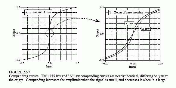
Figure 22-7 graphs these equations for the input variable, x, being between -1 and +1, resulting in the output variable also assuming values between -1 and +1. Equations 22-1 and 22-2 only handle positive input values; portions of the curves for negative input values are found from symmetry. As shown in (a), the curves for μ255 law and "A" law are nearly identical. The only significant difference is near the origin, shown in (b), where μ255 law is a smooth curve, and "A" law switches to a straight line.
Producing a stable nonlinearity is a difficult task for analog electronics. One method is to use the logarithmic relationship between current and

voltage across a pn diode junction, and then add circuitry to correct for the ghastly temperature drift. Most companding circuits take another strategy: approximate the nonlinearity with a group of straight lines. A typical scheme is to approximate the logarithmic curve with a group of 16 straight segments, called cords. The first bit of the 8 bit output indicates if the input is positive or negative. The next three bits identify which of the 8 positive or 8 negative cords is used. The last four bits break each cord into 16 equally spaced increments. As with most integrated circuits, companding chips have sophisticated and proprietary internal designs. Rather than worrying about what goes on inside of the chip, pay the most attention to the pinout and the specification sheet.
