The Scientist and Engineer's Guide to
Digital Signal Processing
By Steven W. Smith, Ph.D.
Book Search

Table of contents
- 1: The Breadth and Depth of DSP
- 2: Statistics, Probability and Noise
- 3: ADC and DAC
- 4: DSP Software
- 5: Linear Systems
- 6: Convolution
- 7: Properties of Convolution
- 8: The Discrete Fourier Transform
- 9: Applications of the DFT
- 10: Fourier Transform Properties
- 11: Fourier Transform Pairs
- 12: The Fast Fourier Transform
- 13: Continuous Signal Processing
- 14: Introduction to Digital Filters
- 15: Moving Average Filters
- 16: Windowed-Sinc Filters
- 17: Custom Filters
- 18: FFT Convolution
- 19: Recursive Filters
- 20: Chebyshev Filters
- 21: Filter Comparison
- 22: Audio Processing
- 23: Image Formation & Display
- 24: Linear Image Processing
- 25: Special Imaging Techniques
- 26: Neural Networks (and more!)
- 27: Data Compression
- 28: Digital Signal Processors
- 29: Getting Started with DSPs
- 30: Complex Numbers
- 31: The Complex Fourier Transform
- 32: The Laplace Transform
- 33: The z-Transform
- 34: Explaining Benford's Law
How to order your own hardcover copy
Wouldn't you rather have a bound book instead of 640 loose pages?Your laser printer will thank you!
Order from Amazon.com.
Chapter 2: Statistics, Probability and Noise
A signal is a description of how one parameter depends on another parameter. For example, the most common type of signal in analog electronics is a voltage that varies with time. Since both parameters can assume a continuous range of values, we will call this a continuous signal. In comparison, passing this signal through an analog-to-digital converter forces each of the two parameters to be quantized. For instance, imagine the conversion being done with 12 bits at a sampling rate of one kilohertz. The voltage is curtailed to 4096 possible binary levels, and the time is only defined at one millisecond increments. Signals formed from parameters that are quantized in this manner are said to be discrete signals or digitized signals. For the most part, continuous signals exist in nature, while discrete signals exist inside computers (although you can find exceptions to both cases). It is also possible to have signals where one parameter is continuous and the other is discrete. Since these mixed signals are quite uncommon, they do not have special names given to them, and the nature of the two parameters must be explicitly stated.
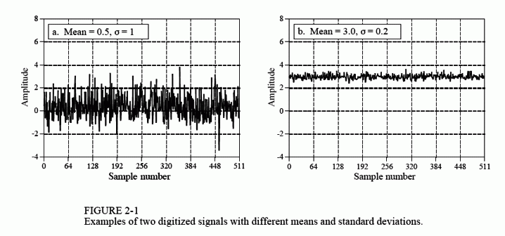
Figure 2-1 shows two discrete signals, such as might be acquired with a digital data acquisition system. The vertical axis may represent voltage, light intensity, sound pressure, or an infinite number of other parameters. Since we don't know what it represents in this particular case, we will give it the generic label: amplitude. This parameter is also called several other names: the y-axis, the dependent variable, the range, and the ordinate.
The horizontal axis represents the other parameter of the signal, going by such names as: the x-axis, the independent variable, the domain, and the abscissa. Time is the most common parameter to appear on the horizontal axis of acquired signals; however, other parameters are used in specific applications. For example, a geophysicist might acquire measurements of rock density at equally spaced distances along the surface of the earth. To keep things general, we will simply label the horizontal axis: sample number. If this were a continuous signal, another label would have to be used, such as: time, distance, x, etc.
The two parameters that form a signal are generally not interchangeable. The parameter on the y-axis (the dependent variable) is said to be a function of the parameter on the x-axis (the independent variable). In other words, the independent variable describes how or when each sample is taken, while the dependent variable is the actual measurement. Given a specific value on the x-axis, we can always find the corresponding value on the y-axis, but usually not the other way around.
Pay particular attention to the word: domain, a very widely used term in DSP. For instance, a signal that uses time as the independent variable (i.e., the parameter on the horizontal axis), is said to be in the time domain. Another common signal in DSP uses frequency as the independent variable, resulting in the term, frequency domain. Likewise, signals that use distance as the independent parameter are said to be in the spatial domain (distance is a measure of space). The type of parameter on the horizontal axis is the domain of the signal; it's that simple. What if the x-axis is labeled with something very generic, such as sample number? Authors commonly refer to these signals as being in the time domain. This is because sampling at equal intervals of time is the most common way of obtaining signals, and they don't have anything more specific to call it.
Although the signals in Fig. 2-1 are discrete, they are displayed in this figure as continuous lines. This is because there are too many samples to be distinguishable if they were displayed as individual markers. In graphs that portray shorter signals, say less than 100 samples, the individual markers are usually shown. Continuous lines may or may not be drawn to connect the markers, depending on how the author wants you to view the data. For instance, a continuous line could imply what is happening between samples, or simply be an aid to help the reader's eye follow a trend in noisy data. The point is, examine the labeling of the horizontal axis to find if you are working with a discrete or continuous signal. Don't rely on an illustrator's ability to draw dots.
The variable, N, is widely used in DSP to represent the total number of samples in a signal. For example, N = 512 for the signals in Fig. 2-1. To
keep the data organized, each sample is assigned a sample number or index. These are the numbers that appear along the horizontal axis. Two notations for assigning sample numbers are commonly used. In the first notation, the sample indexes run from 1 to N (e.g., 1 to 512). In the second notation, the sample indexes run from 0 to N`-`1 (e.g., 0 to 511). Mathematicians often use the first method (1 to N), while those in DSP commonly uses the second (0 to N`-`1). In this book, we will use the second notation. Don't dismiss this as a trivial problem. It will confuse you sometime during your career. Look out for it!