The Scientist and Engineer's Guide to
Digital Signal Processing
By Steven W. Smith, Ph.D.
Book Search
Table of contents
- 1: The Breadth and Depth of DSP
- 2: Statistics, Probability and Noise
- 3: ADC and DAC
- 4: DSP Software
- 5: Linear Systems
- 6: Convolution
- 7: Properties of Convolution
- 8: The Discrete Fourier Transform
- 9: Applications of the DFT
- 10: Fourier Transform Properties
- 11: Fourier Transform Pairs
- 12: The Fast Fourier Transform
- 13: Continuous Signal Processing
- 14: Introduction to Digital Filters
- 15: Moving Average Filters
- 16: Windowed-Sinc Filters
- 17: Custom Filters
- 18: FFT Convolution
- 19: Recursive Filters
- 20: Chebyshev Filters
- 21: Filter Comparison
- 22: Audio Processing
- 23: Image Formation & Display
- 24: Linear Image Processing
- 25: Special Imaging Techniques
- 26: Neural Networks (and more!)
- 27: Data Compression
- 28: Digital Signal Processors
- 29: Getting Started with DSPs
- 30: Complex Numbers
- 31: The Complex Fourier Transform
- 32: The Laplace Transform
- 33: The z-Transform
- 34: Explaining Benford's Law
How to order your own hardcover copy
Wouldn't you rather have a bound book instead of 640 loose pages?Your laser printer will thank you!
Order from Amazon.com.
Chapter 5: Linear Systems
Homogeneity, additivity, and shift invariance are important because they provide the mathematical basis for defining linear systems. Unfortunately, these properties alone don't provide most scientists and engineers with an intuitive feeling of what linear systems are about. The properties of static linearity and sinusoidal fidelity are often of help here. These are not especially important from a mathematical standpoint, but relate to how humans think about and understand linear systems. You should pay special attention to this section.
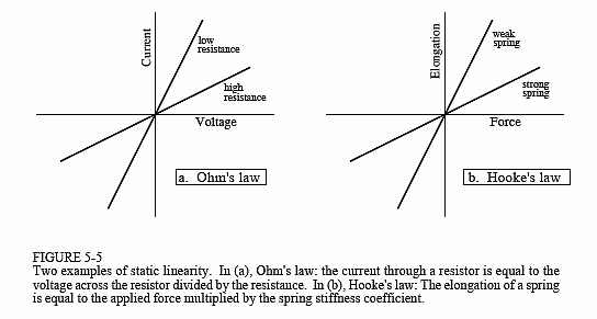
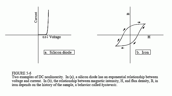
Static linearity defines how a linear system reacts when the signals aren't changing, i.e., when they are DC or static. The static response of a linear system is very simple: the output is the input multiplied by a constant. That is, a graph of the possible input values plotted against the corresponding output values is a straight line that passes through the origin. This is shown in Fig. 5-5 for two common linear systems: Ohm's law for resistors, and Hooke's law for springs. For comparison, Fig. 5-6 shows the static relationship for two nonlinear systems: a pn junction diode, and the magnetic properties of iron.

All linear systems have the property of static linearity. The opposite is usually true, but not always. There are systems that show static linearity, but are not linear with respect to changing signals. However, a very common class of systems can be completely understood with static linearity alone. In these systems it doesn't matter if the input signal is static or changing. These are called memoryless systems, because the output depends only on the present state of the input, and not on its history. For example, the instantaneous current in a resistor depends only on the instantaneous voltage across it, and not on how the signals came to be the value they are. If a system has static linearity, and is memoryless, then the system must be linear. This provides an important way to understand (and prove) the linearity of these simple systems.

An important characteristic of linear systems is how they behave with sinusoids, a property we will call sinusoidal fidelity: If the input to a linear system is a sinusoidal wave, the output will also be a sinusoidal wave, and at exactly the same frequency as the input. Sinusoids are the only waveform that have this property. For instance, there is no reason to expect that a square wave entering a linear system will produce a square wave on the output. Although a sinusoid on the input guarantees a sinusoid on the output, the two may be different in amplitude and phase. This should be familiar from your knowledge of electronics: a circuit can be described by its frequency response, graphs of how the circuit's gain and phase vary with frequency.
Now for the reverse question: If a system always produces a sinusoidal output in response to a sinusoidal input, is the system guaranteed to be linear? The answer is no, but the exceptions are rare and usually obvious. For example, imagine an evil demon hiding inside a system, with the goal of trying to mislead you. The demon has an oscilloscope to observe the input signal, and a sine wave generator to produce an output signal. When you feed a sine wave into the input, the demon quickly measures the frequency and adjusts his signal generator to produce a corresponding output. Of course, this system is not linear, because it is not additive. To show this, place the sum of two sine waves into the system. The demon can only respond with a single sine wave for the output. This example is not as contrived as you might think; phase lock loops operate in much this way.
To get a better feeling for linearity, think about a technician trying to determine if an electronic device is linear. The technician would attach a sine wave generator to the input of the device, and an oscilloscope to the output. With a sine wave input, the technician would look to see if the output is also a sine wave. For example, the output cannot be clipped on the top or bottom, the top half cannot look different from the bottom half, there must be no distortion where the signal crosses zero, etc. Next, the technician would vary the amplitude of the input and observe the effect on the output signal. If the system is linear, the amplitude of the output must track the amplitude of the input. Lastly, the technician would vary the input signal's frequency, and verify that the output signal's frequency changes accordingly. As the frequency is changed, there will likely be amplitude and phase changes seen in the output, but these are perfectly permissible in a linear system. At some frequencies, the output may even be zero, that is, a sinusoid with zero amplitude. If the technician sees all these things, he will conclude that the system is linear. While this conclusion is not a rigorous mathematical proof, the level of confidence is justifiably high.
