The Scientist and Engineer's Guide to
Digital Signal Processing
By Steven W. Smith, Ph.D.
Book Search
Table of contents
- 1: The Breadth and Depth of DSP
- 2: Statistics, Probability and Noise
- 3: ADC and DAC
- 4: DSP Software
- 5: Linear Systems
- 6: Convolution
- 7: Properties of Convolution
- 8: The Discrete Fourier Transform
- 9: Applications of the DFT
- 10: Fourier Transform Properties
- 11: Fourier Transform Pairs
- 12: The Fast Fourier Transform
- 13: Continuous Signal Processing
- 14: Introduction to Digital Filters
- 15: Moving Average Filters
- 16: Windowed-Sinc Filters
- 17: Custom Filters
- 18: FFT Convolution
- 19: Recursive Filters
- 20: Chebyshev Filters
- 21: Filter Comparison
- 22: Audio Processing
- 23: Image Formation & Display
- 24: Linear Image Processing
- 25: Special Imaging Techniques
- 26: Neural Networks (and more!)
- 27: Data Compression
- 28: Digital Signal Processors
- 29: Getting Started with DSPs
- 30: Complex Numbers
- 31: The Complex Fourier Transform
- 32: The Laplace Transform
- 33: The z-Transform
- 34: Explaining Benford's Law
How to order your own hardcover copy
Wouldn't you rather have a bound book instead of 640 loose pages?Your laser printer will thank you!
Order from Amazon.com.
Chapter 11: Fourier Transform Pairs
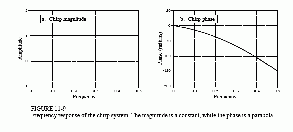
Chirp signals are an ingenious way of handling a practical problem in echo location systems, such as radar and sonar. Figure 11-9 shows the frequency response of the chirp system. The magnitude has a constant value of one, while the phase is a parabola:


The parameter α introduces a linear slope in the phase, that is, it simply shifts the impulse response left or right as desired. The parameter ? controls the curvature of the phase. These two parameters must be chosen such that the phase at frequency 0.5 (i.e. k = N/2) is a multiple of 2π. Remember, whenever the phase is directly manipulated, frequency 0 and 0.5 must both have a phase of zero (or a multiple of 2π, which is the same thing).
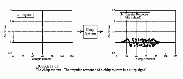
Figure 11-10 shows an impulse entering a chirp system, and the impulse response exiting the system. The impulse response is an oscillatory burst that starts at a low frequency and changes to a high frequency as time progresses. This is called a chirp signal for a very simple reason: it sounds like the chirp of a bird when played through a speaker.
The key feature of the chirp system is that it is completely reversible. If you run the chirp signal through an antichirp system, the signal is again made into an impulse. This requires the antichirp system to have a magnitude of one, and the opposite phase of the chirp system. As discussed in the last

chapter, this means that the impulse response of the antichirp system is found by preforming a left-for-right flip of the chirp system's impulse response. Interesting, but what is it good for?
Consider how a radar system operates. A short burst of radio frequency energy is emitted from a directional antenna. Aircraft and other objects reflect some of this energy back to a radio receiver located next to the transmitter. Since radio waves travel at a constant rate, the elapsed time between the transmitted and received signals provides the distance to the target. This brings up the first requirement for the pulse: it needs to be as short as possible. For example, a 1 microsecond pulse provides a radio burst about 300 meters long. This means that the distance information we obtain with the system will have a resolution of about this same length. If we want better distance resolution, we need a shorter pulse.
The second requirement is obvious: if we want to detect objects farther away, you need more energy in your pulse. Unfortunately, more energy and shorter pulse are conflicting requirements. The electrical power needed to provide a pulse is equal to the energy of the pulse divided by the pulse length. Requiring both more energy and a shorter pulse makes electrical power handling a limiting factor in the system. The output stage of a radio transmitter can only handle so much power without destroying itself.
Chirp signals provide a way of breaking this limitation. Before the impulse reaches the final stage of the radio transmitter, it is passed through a chirp system. Instead of bouncing an impulse off the target aircraft, a chirp signal is used. After the chirp echo is received, the signal is passed through an antichirp system, restoring the signal to an impulse. This allows the portions of the system that measure distance to see short pulses, while the power handling circuits see long duration signals. This type of waveshaping is a fundamental part of modern radar systems.
