The Scientist and Engineer's Guide to
Digital Signal Processing
By Steven W. Smith, Ph.D.
Book Search
Table of contents
- 1: The Breadth and Depth of DSP
- 2: Statistics, Probability and Noise
- 3: ADC and DAC
- 4: DSP Software
- 5: Linear Systems
- 6: Convolution
- 7: Properties of Convolution
- 8: The Discrete Fourier Transform
- 9: Applications of the DFT
- 10: Fourier Transform Properties
- 11: Fourier Transform Pairs
- 12: The Fast Fourier Transform
- 13: Continuous Signal Processing
- 14: Introduction to Digital Filters
- 15: Moving Average Filters
- 16: Windowed-Sinc Filters
- 17: Custom Filters
- 18: FFT Convolution
- 19: Recursive Filters
- 20: Chebyshev Filters
- 21: Filter Comparison
- 22: Audio Processing
- 23: Image Formation & Display
- 24: Linear Image Processing
- 25: Special Imaging Techniques
- 26: Neural Networks (and more!)
- 27: Data Compression
- 28: Digital Signal Processors
- 29: Getting Started with DSPs
- 30: Complex Numbers
- 31: The Complex Fourier Transform
- 32: The Laplace Transform
- 33: The z-Transform
- 34: Explaining Benford's Law
How to order your own hardcover copy
Wouldn't you rather have a bound book instead of 640 loose pages?Your laser printer will thank you!
Order from Amazon.com.
Chapter 12: The Fast Fourier Transform
The FFT is a complicated algorithm, and its details are usually left to those that specialize in such things. This section describes the general operation of the FFT, but skirts a key issue: the use of complex numbers. If you have a background in complex mathematics, you can read between the lines to understand the true nature of the algorithm. Don't worry if the details elude you; few scientists and engineers that use the FFT could write the program from scratch.
In complex notation, the time and frequency domains each contain one signal made up of N complex points. Each of these complex points is composed of two numbers, the real part and the imaginary part. For example, when we talk about complex sample X[42], it refers to the combination of ReX[42] and ImX[42]. In other words, each complex variable holds two numbers. When two complex variables are multiplied, the four individual components must be combined to form the two components of the product (such as in Eq. 9-1). The following discussion on "How the FFT works" uses this jargon of complex notation. That is, the singular terms: signal, point, sample, and value, refer to the combination of the real part and the imaginary part.
The FFT operates by decomposing an N point time domain signal into N time domain signals each composed of a single point. The second step is to calculate the N frequency spectra corresponding to these N time domain signals. Lastly, the N spectra are synthesized into a single frequency spectrum.
Figure 12-2 shows an example of the time domain decomposition used in the FFT. In this example, a 16 point signal is decomposed through four
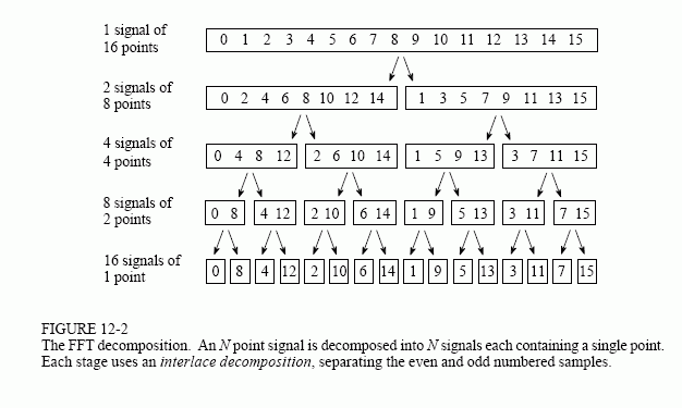
separate stages. The first stage breaks the 16 point signal into two signals each consisting of 8 points. The second stage decomposes the data into four signals of 4 points. This pattern continues until there are N signals composed of a single point. An interlaced decomposition is used each time a signal is broken in two, that is, the signal is separated into its even and odd numbered samples. The best way to understand this is by inspecting Fig. 12-2 until you grasp the pattern. There are Log2N stages required in this decomposition, i.e., a 16 point signal (24) requires 4 stages, a 512 point signal (27) requires 7 stages, a 4096 point signal (212) requires 12 stages, etc. Remember this value, Log2N; it will be referenced many times in this chapter.
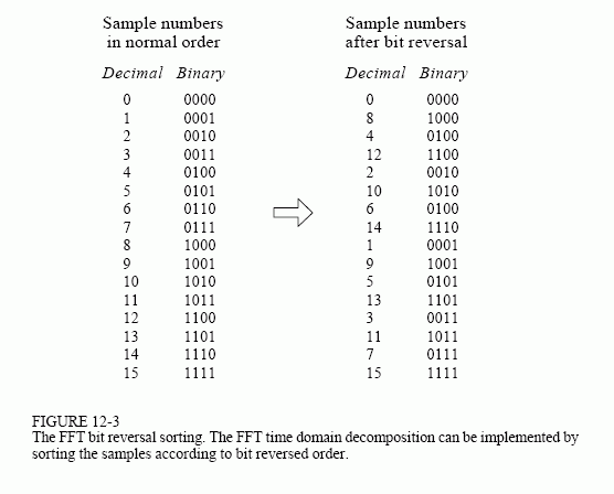
Now that you understand the structure of the decomposition, it can be greatly simplified. The decomposition is nothing more than a reordering of the samples in the signal. Figure 12-3 shows the rearrangement pattern required. On the left, the sample numbers of the original signal are listed along with their binary equivalents. On the right, the rearranged sample numbers are listed, also along with their binary equivalents. The important idea is that the binary numbers are the reversals of each other. For example, sample 3 (0011) is exchanged with sample number 12 (1100). Likewise, sample number 14 (1110) is swapped with sample number 7 (0111), and so forth. The FFT time domain decomposition is usually carried out by a bit reversal sorting algorithm. This involves rearranging the order of the N time domain samples by counting in binary with the bits flipped left-for-right (such as in the far right column in Fig. 12-3).
The next step in the FFT algorithm is to find the frequency spectra of the 1 point time domain signals. Nothing could be easier; the frequency spectrum of a 1 point signal is equal to itself. This means that nothing is required to do this step. Although there is no work involved, don't forget that each of the 1 point signals is now a frequency spectrum, and not a time domain signal.
The last step in the FFT is to combine the N frequency spectra in the exact reverse order that the time domain decomposition took place. This is where the algorithm gets messy. Unfortunately, the bit reversal shortcut is not applicable, and we must go back one stage at a time. In the first stage, 16 frequency spectra (1 point each) are synthesized into 8 frequency spectra (2 points each). In the second stage, the 8 frequency spectra (2 points each) are synthesized into 4 frequency spectra (4 points each), and so on. The last stage results in the output of the FFT, a 16 point frequency spectrum.
Figure 12-4 shows how two frequency spectra, each composed of 4 points, are combined into a single frequency spectrum of 8 points. This synthesis must undo the interlaced decomposition done in the time domain. In other words, the frequency domain operation must correspond to the time domain procedure of combining two 4 point signals by interlacing. Consider two time domain signals, abcd and efgh. An 8 point time domain signal can be formed by two steps: dilute each 4 point signal with zeros to make it an
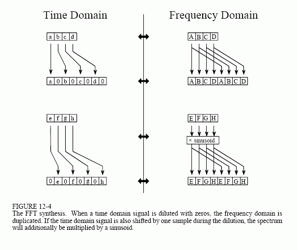
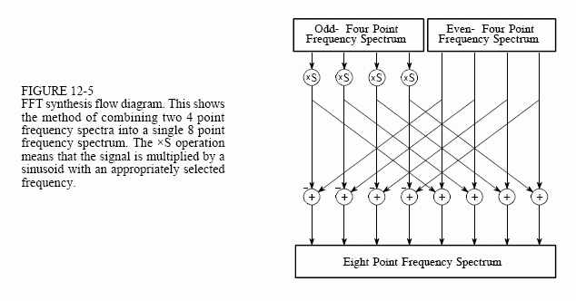
8 point signal, and then add the signals together. That is, abcd becomes a0b0c0d0, and efgh becomes 0e0f0g0h. Adding these two 8 point signals produces aebfcgdh. As shown in Fig. 12-4, diluting the time domain with zeros corresponds to a duplication of the frequency spectrum. Therefore, the frequency spectra are combined in the FFT by duplicating them, and then adding the duplicated spectra together.
In order to match up when added, the two time domain signals are diluted with zeros in a slightly different way. In one signal, the odd points are zero, while in the other signal, the even points are zero. In other words, one of the time domain signals (0e0f0g0h in Fig. 12-4) is shifted to the right by one sample. This time domain shift corresponds to multiplying the spectrum by a sinusoid. To see this, recall that a shift in the time domain is equivalent to convolving the signal with a shifted delta function. This multiplies the signal's spectrum with the spectrum of the shifted delta function. The spectrum of a shifted delta function is a sinusoid (see Fig 11-2).
Figure 12-5 shows a flow diagram for combining two 4 point spectra into a single 8 point spectrum. To reduce the situation even more, notice that Fig. 12-5 is formed from the basic pattern in Fig 12-6 repeated over and over.
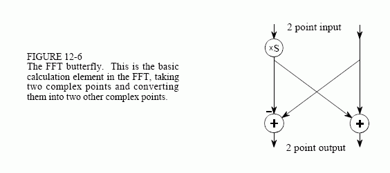
This simple flow diagram is called a butterfly due to its winged appearance. The butterfly is the basic computational element of the FFT, transforming two complex points into two other complex points.
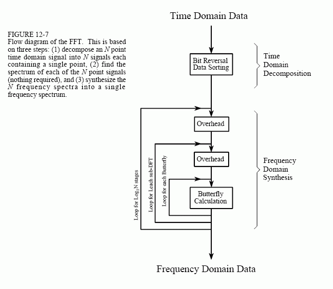
Figure 12-7 shows the structure of the entire FFT. The time domain decomposition is accomplished with a bit reversal sorting algorithm. Transforming the decomposed data into the frequency domain involves nothing and therefore does not appear in the figure.
The frequency domain synthesis requires three loops. The outer loop runs through the Log2N stages (i.e., each level in Fig. 12-2, starting from the bottom and moving to the top). The middle loop moves through each of the individual frequency spectra in the stage being worked on (i.e., each of the boxes on any one level in Fig. 12-2). The innermost loop uses the butterfly to calculate the points in each frequency spectra (i.e., looping through the samples inside any one box in Fig. 12-2). The overhead boxes in Fig. 12-7 determine the beginning and ending indexes for the loops, as well as calculating the sinusoids needed in the butterflies. Now we come to the heart of this chapter, the actual FFT programs.
