The Scientist and Engineer's Guide to
Digital Signal Processing
By Steven W. Smith, Ph.D.
Book Search
Table of contents
- 1: The Breadth and Depth of DSP
- 2: Statistics, Probability and Noise
- 3: ADC and DAC
- 4: DSP Software
- 5: Linear Systems
- 6: Convolution
- 7: Properties of Convolution
- 8: The Discrete Fourier Transform
- 9: Applications of the DFT
- 10: Fourier Transform Properties
- 11: Fourier Transform Pairs
- 12: The Fast Fourier Transform
- 13: Continuous Signal Processing
- 14: Introduction to Digital Filters
- 15: Moving Average Filters
- 16: Windowed-Sinc Filters
- 17: Custom Filters
- 18: FFT Convolution
- 19: Recursive Filters
- 20: Chebyshev Filters
- 21: Filter Comparison
- 22: Audio Processing
- 23: Image Formation & Display
- 24: Linear Image Processing
- 25: Special Imaging Techniques
- 26: Neural Networks (and more!)
- 27: Data Compression
- 28: Digital Signal Processors
- 29: Getting Started with DSPs
- 30: Complex Numbers
- 31: The Complex Fourier Transform
- 32: The Laplace Transform
- 33: The z-Transform
- 34: Explaining Benford's Law
How to order your own hardcover copy
Wouldn't you rather have a bound book instead of 640 loose pages?Your laser printer will thank you!
Order from Amazon.com.
Chapter 10: Fourier Transform Properties
An important Fourier transform property is that convolution in one domain corresponds to multiplication in the other domain. One side of this was discussed in the last chapter: time domain signals can be convolved by multiplying their frequency spectra. Amplitude modulation is an example of the reverse situation, multiplication in the time domain corresponds to convolution in the frequency domain. In addition, amplitude modulation provides an excellent example of how the elusive negative frequencies enter into everyday science and engineering problems.
Audio signals are great for short distance communication; when you speak, someone across the room hears you. On the other hand, radio frequencies are very good at propagating long distances. For instance, if a 100 volt, 1 MHz sine wave is fed into an antenna, the resulting radio wave can be detected in the next room, the next country, and even on the next planet. Modulation is the process of merging two signals to form a third signal with desirable characteristics of both. This always involves nonlinear processes such as multiplication; you can't just add the two signals together. In radio communication, modulation results in radio signals that can propagate long distances and carry along audio or other information.
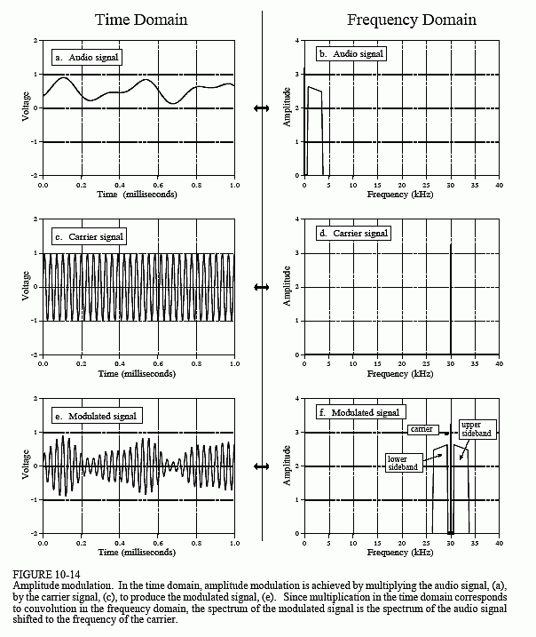
Radio communication is an extremely well developed discipline, and many modulation schemes have been developed. One of the simplest is called amplitude modulation. Figure 10-14 shows an example of how amplitude modulation appears in both the time and frequency domains. Continuous signals will be used in this example, since modulation is usually carried out in analog electronics. However, the whole procedure could be carried out in discrete form if needed (the shape of the future!).
Figure (a) shows an audio signal with a DC bias such that the signal always has a positive value. Figure (b) shows that its frequency spectrum is composed of frequencies from 300 Hz to 3 kHz, the range needed for voice communication, plus a spike for the DC component. All other frequencies have been removed by analog filtering. Figures (c) and (d) show the carrier wave, a pure sinusoid of much higher frequency than the audio signal. In the time domain, amplitude modulation consists of multiplying the audio signal by the carrier wave. As shown in (e), this results in an oscillatory waveform that has an instantaneous amplitude proportional to the original audio signal. In the jargon of the field, the envelope of the carrier wave is equal to the modulating signal. This signal can be routed to an antenna, converted into a radio wave, and then detected by a receiving antenna. This results in a signal identical to (e) being generated in the radio receiver's electronics. A detector or demodulator circuit is then used to convert the waveform in (e) back into the waveform in (a).
Since the time domain signals are multiplied, the corresponding frequency spectra are convolved. That is, (f) is found by convolving (b) & (d). Since the spectrum of the carrier is a shifted delta function, the spectrum of the

modulated signal is equal to the audio spectrum shifted to the frequency of the carrier. This results in a modulated spectrum composed of three components: a carrier wave, an upper sideband, and a lower sideband.
These correspond to the three parts of the original audio signal: the DC component, the positive frequencies between 0.3 and 3 kHz, and the negative frequencies between -0.3 and -3 kHz, respectively. Even though the negative frequencies in the original audio signal are somewhat elusive and abstract, the resulting frequencies in the lower sideband are as real as you could want them to be. The ghosts have taken human form!
Communication engineers live and die by this type of frequency domain analysis. For example, consider the frequency spectrum for television transmission. A standard TV signal has a frequency spectrum from DC to 6 MHz. By using these frequency shifting techniques, 82 of these 6 MHz wide channels are stacked on top of each other. For instance, channel 3 is from 60 to 66 MHz, channel 4 is from 66 to 72 MHz, channel 83 is from 884 to 890 MHz, etc. The television receiver moves the desired channel back to the DC to 6 MHz band for display on the screen. This scheme is called frequency domain multiplexing.
