The Scientist and Engineer's Guide to
Digital Signal Processing
By Steven W. Smith, Ph.D.
Book Search
Table of contents
- 1: The Breadth and Depth of DSP
- 2: Statistics, Probability and Noise
- 3: ADC and DAC
- 4: DSP Software
- 5: Linear Systems
- 6: Convolution
- 7: Properties of Convolution
- 8: The Discrete Fourier Transform
- 9: Applications of the DFT
- 10: Fourier Transform Properties
- 11: Fourier Transform Pairs
- 12: The Fast Fourier Transform
- 13: Continuous Signal Processing
- 14: Introduction to Digital Filters
- 15: Moving Average Filters
- 16: Windowed-Sinc Filters
- 17: Custom Filters
- 18: FFT Convolution
- 19: Recursive Filters
- 20: Chebyshev Filters
- 21: Filter Comparison
- 22: Audio Processing
- 23: Image Formation & Display
- 24: Linear Image Processing
- 25: Special Imaging Techniques
- 26: Neural Networks (and more!)
- 27: Data Compression
- 28: Digital Signal Processors
- 29: Getting Started with DSPs
- 30: Complex Numbers
- 31: The Complex Fourier Transform
- 32: The Laplace Transform
- 33: The z-Transform
- 34: Explaining Benford's Law
How to order your own hardcover copy
Wouldn't you rather have a bound book instead of 640 loose pages?Your laser printer will thank you!
Order from Amazon.com.
Chapter 22: Audio Processing
Audiophiles demand the utmost sound quality, and all other factors are treated as secondary. If you had to describe the mindset in one word, it would be: overkill. Rather than just matching the abilities of the human ear, these systems are designed to exceed the limits of hearing. It's the only way to be sure that the reproduced music is pristine. Digital audio was brought to the world by the compact laser disc, or CD. This was a revolution in music; the sound quality of the CD system far exceeds older systems, such as records and tapes. DSP has been at the forefront of this technology.
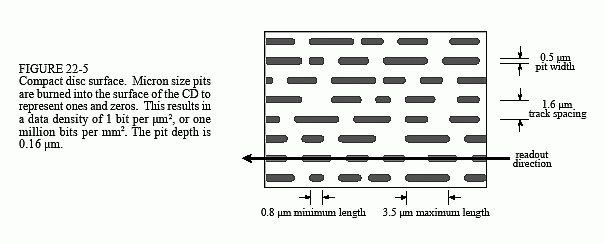
Figure 22-5 illustrates the surface of a compact laser disc, such as viewed through a high power microscope. The main surface is shiny (reflective of light), with the digital information stored as a series of dark pits burned on the surface with a laser. The information is arranged in a single track that spirals from the outside to the inside, the same as a phonograph record. The rotation of the CD is changed from about 210 to 480 rpm as the information is read from the outside to the inside of the spiral, making the scanning velocity a constant 1.2 meters per second. (In comparison, phonograph records spin at a fixed rate, such as 33, 45 or 78 rpm). During playback, an optical sensor detects if the surface is reflective or nonreflective, generating the corresponding binary information.
As shown by the geometry in Fig. 22-5, the CD stores about 1 bit per (μ)2, corresponding to 1 million bits per (mm)2, and 15 billion bits per disk. This is about the same feature size used in integrated circuit manufacturing, and for a good reason. One of the properties of light is that it cannot be focused to smaller than about one-half wavelength, or 0.3 μm. Since both integrated circuits and laser disks are created by optical means, the fuzziness of light below 0.3 μm limits how small of features can be used.
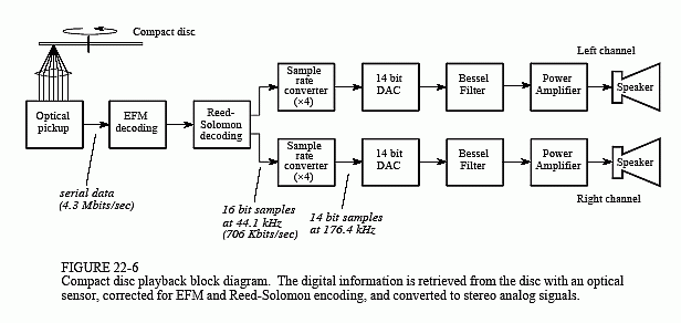
Figure 22-6 shows a block diagram of a typical compact disc playback system. The raw data rate is 4.3 million bits per second, corresponding to 1 bit each 0.28 μm of track length. However, this is in conflict with the specified geometry of the CD; each pit must be no shorter than 0.8 μm, and no longer than 3.5 μm. In other words, each binary one must be part of a group of 3 to 13 ones. This has the advantage of reducing the error rate due to the optical pickup, but how do you force the binary data to comply with this strange bunching?
The answer is an encoding scheme called eight-to-fourteen modulation (EFM). Instead of directly storing a byte of data on the disc, the 8 bits are passed through a look-up table that pops out 14 bits. These 14 bits have the desired bunching characteristics, and are stored on the laser disc. Upon playback, the binary values read from the disc are passed through the inverse of the EFM look-up table, resulting in each 14 bit group being turned back into the correct 8 bits.


In addition to EFM, the data are encoded in a format called two-level Reed-Solomon coding. This involves combining the left and right stereo channels along with data for error detection and correction. Digital errors detected during playback are either: corrected by using the redundant data in the encoding scheme, concealed by interpolating between adjacent samples, or muted by setting the sample value to zero. These encoding schemes result in the data rate being tripled, i.e., 1.4 Mbits/sec for the stereo audio signals versus 4.3 Mbits/sec stored on the disc.
After decoding and error correction, the audio signals are represented as 16 bit samples at a 44.1 kHz sampling rate. In the simplest system, these signals could be run through a 16 bit DAC, followed by a low-pass analog filter. However, this would require high performance analog electronics to pass frequencies below 20 kHz, while rejecting all frequencies above 22.05 kHz, ½ of the sampling rate. A more common method is to use a multirate technique, that is, convert the digital data to a higher sampling rate before the DAC. A factor of four is commonly used, converting from 44.1 kHz to 176.4 kHz. This is called interpolation, and can be explained as a two step process (although it may not actually be carried out this way). First, three samples with a value of zero are placed between the original samples, producing the higher sampling rate. In the frequency domain, this has the effect of duplicating the 0 to 22.05 kHz spectrum three times, at 22.05 to 44.1 kHz, 41 to 66.15 kHz, and 66.15 to 88.2 kHz. In the second step, an efficient digital filter is used to remove the newly added frequencies.
The sample rate increase makes the sampling interval smaller, resulting in a smoother signal being generated by the DAC. The signal still contains frequencies between 20 Hz and 20 kHz; however, the Nyquist frequency has been increased by a factor of four. This means that the analog filter only needs to pass frequencies below 20 kHz, while blocking frequencies above 88.2 kHz. This is usually done with a three pole Bessel filter. Why use a Bessel filter if the ear is insensitive to phase? Overkill, remember?
Since there are four times as many samples, the number of bits per sample can be reduced from 16 bits to 14 bits, without degrading the sound quality. The sin(x)/x correction needed to compensate for the zeroth order hold of the DAC can be part of either the analog or digital filter.
Audio systems with more than one channel are said to be in stereo (from the Greek word for solid, or three-dimensional). Multiple channels send sound to the listener from different directions, providing a more accurate reproduction of the original music. Music played through a monaural (one channel) system often sounds artificial and bland. In comparison, a good stereo reproduction makes the listener feel as if the musicians are only a few feet away. Since the 1960s, high fidelity music has used two channels (left and right), while motion pictures have used four channels (left, right, center, and surround). In early stereo recordings (say, the Beatles or the Mamas And The Papas), individual singers can often be heard in only one channel or the other. This rapidly progressed into a more sophisticated mix-down, where the sound from many microphones in the recording studio is combined into the two channels. Mix-down is an art, aimed at providing the listener with the perception of being there.
The four channel sound used in motion pictures is called Dolby Stereo, with the home version called Dolby Surround Pro Logic. ("Dolby" and "Pro Logic" are trademarks of Dolby Laboratories Licensing Corp.). The four channels are encoded into the standard left and right channels, allowing regular two-channel stereo systems to reproduce the music. A Dolby decoder is used during playback to recreate the four channels of sound. The left and right channels, from speakers placed on each side of the movie or television screen, is similar to that of a regular two-channel stereo system. The speaker for the center channel is usually placed directly above or below the screen. Its purpose is to reproduce speech and other visually connected sounds, keeping them firmly centered on the screen, regardless of the seating position of the viewer/listener. The surround speakers are placed to the left and right of the listener, and may involve as many as twenty speakers in a large auditorium. The surround channel only contains midrange frequencies (say, 100 Hz to 7 kHz), and is delayed by 15 to 30 milliseconds. This delay makes the listener perceive that speech is coming from the screen, and not the sides. That is, the listener hears the speech coming from the front, followed by a delayed version of the speech coming from the sides. The listener's mind interprets the delayed signal as a reflection from the walls, and ignores it.
